Freezing detection method for fuel cell

a detection method and fuel cell technology, applied in the field of freezing detection method of fuel cells, can solve the problems of increasing energy loss, adversely affecting a member of the fuel cell, water generated within the fuel cell may freeze, etc., and achieves the effect of less malfunction, less energy loss, and precise detection of the freezing of the fuel cell uni

Inactive Publication Date: 2009-08-27
CANON KK
View PDF4 Cites 8 Cited by
  • Summary
  • Abstract
  • Description
  • Claims
  • Application Information

AI Technical Summary

Benefits of technology

[0013]According to the present invention, a phenomenon specific to the time when the water within the fuel cell unit starts to freeze is detected, whereby a prompt and precise detection of the freezing of the fuel cell unit is enabled. As a result, there can be provided a freezing detection method for a fuel cell with a less malfunction and a less energy loss. By utilizing the present invention, it is possible to provide a fuel cell in which damage to a device resulting from a sudden output drop of the output due to freezing can be reduced, and in which degradation due to repeated freezing is suppressed.

Problems solved by technology

When a fuel cell is used under a low-temperature environment, water generated within the fuel cell may freeze.
Depending on a place where freezing occurs, reaction gas intake becomes difficult, which leads to problems such that a sudden output drop gives damage to a connection device, and adversely affects a member constituting the fuel cell.
That is, in the method, the heating unit is activated even in a non-freezing situation, an energy loss increases.
However, as the cause of changes in cell resistance and output power, various factors can be considered, such as load fluctuations, a dry-out phenomenon in which an electrolyte membrane dries, and a flooding phenomenon in which generated water clogs a supply path for a reaction gas.
That is, with the conventional technology described above, it is difficult to distinguish phenomena other than freezing as described above from real freezing so that it is difficult to precisely detect freezing.
Consequently, the conventional technology had the problem that waste of energy may occur due to a malfunction such as the activation of a heating unit in the event of a phenomenon other than freezing.

Method used


Image

  • Freezing detection method for fuel cell
  • Freezing detection method for fuel cell
  • Freezing detection method for fuel cell

Examples


example 1

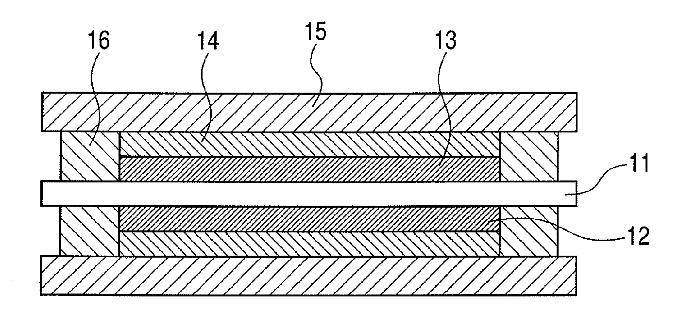
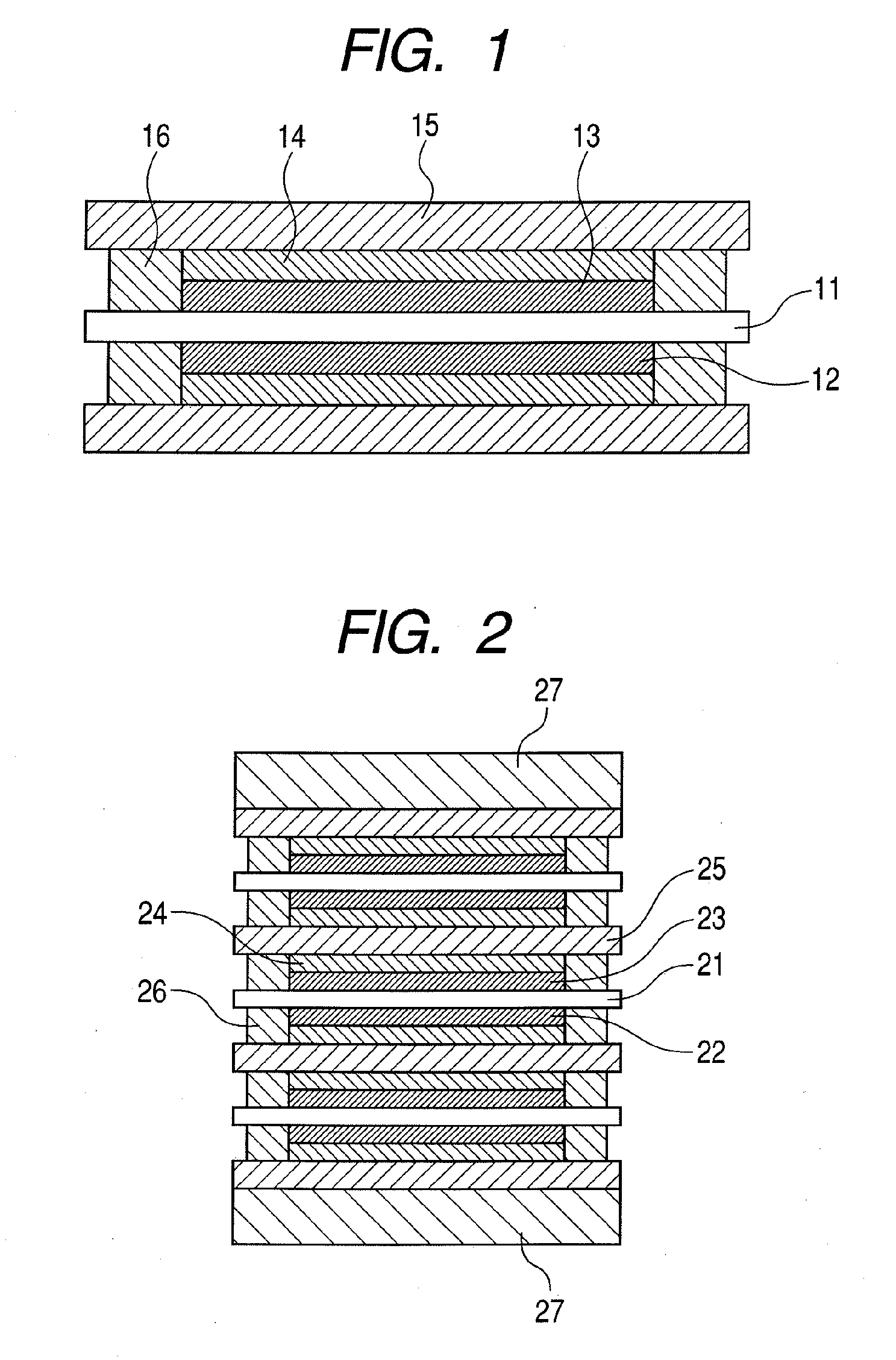
[0058]First, a membrane electrode assembly (MEA) obtained by bonding 2 cm squares of platinum black as the catalyst layers 12 and 13 to both sides of a Nafion (registered trademark of Du Pont Kabushiki Kaisha) as the electrolyte 11 by a hot press was prepared. Then, both sides of the MEA were sandwiched between carbon cloth pieces each as the gas diffusion layer 14, and further sandwiched the MEA from the outside between the collectors 15 obtained by plating SUS with gold and formed with the reaction gas flow paths so as to be fastened. In this manner, a fuel cell as illustrated in FIG. 1 was produced.

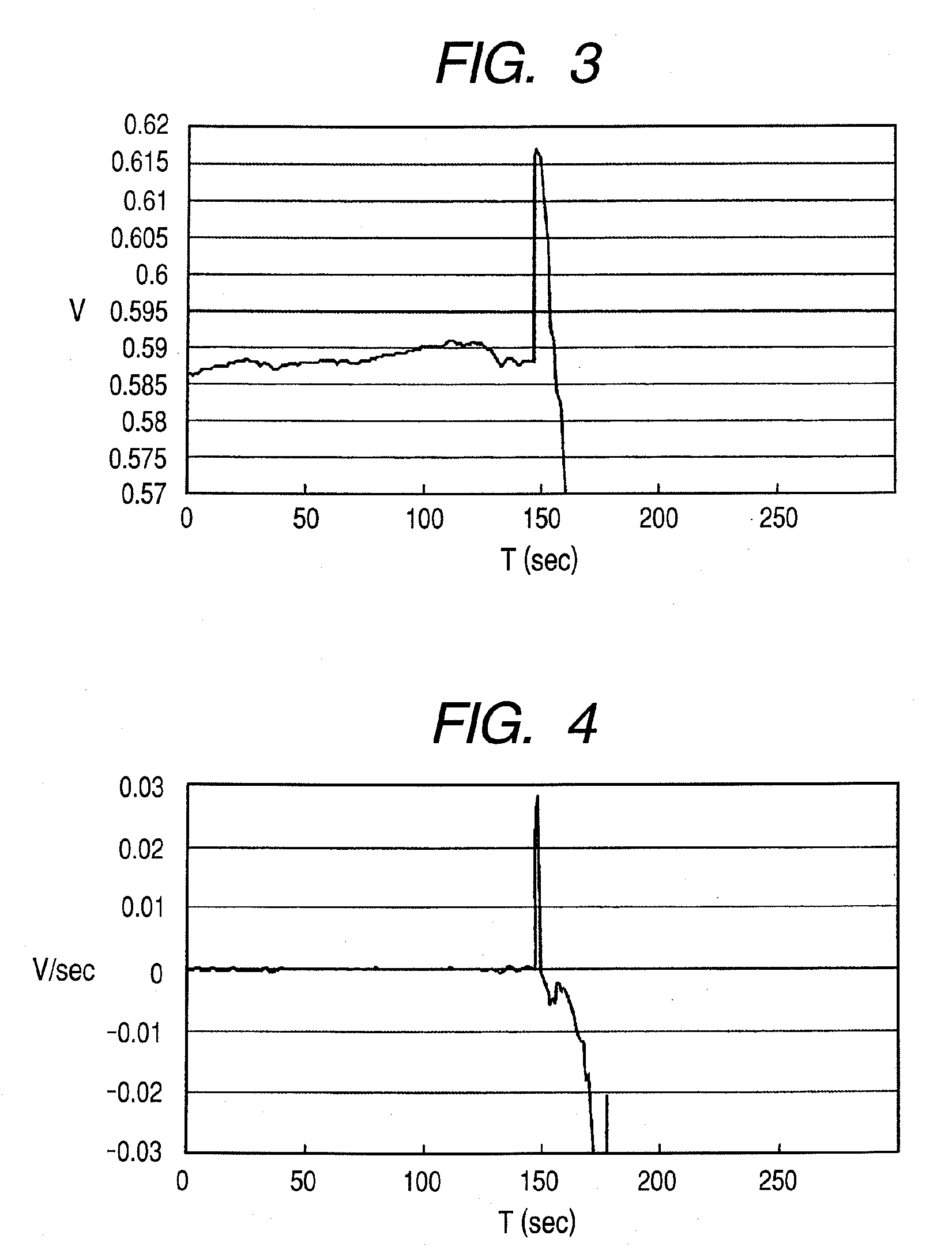
[0059]The fuel cell thus produced was placed in an environment tester, and held in a constant atmosphere at −15° C. for a period of one hour or more. Then, power generation was started with a constant current of 50 mA / cm2. After the power generation was continued for a while, a rise in voltage was observed at a certain time, as illustrated in FIG. 9. The change in voltage indicates tha...

example 2

[0060]Using the same fuel cell as used in Example 1, the same test as conducted in Example 1 was conducted except that freezing was detected using the secondary differential value of the output voltage instead of the differential value thereof. That is, at the time when the secondary differential value of the output voltage reached a value not more than −5 mV / sec2 (second step) after reaching the value not less than 5 mV / sec2 (first step), the fuel cell was heated using a heating unit. In this case also, after heating was performed, the output voltage that had temporarily dropped was gradually recovered to enable the power generation to be continued.

example 3

[0061]In Example 3, the fuel cells produced in Example 1 were stacked in a 3-cell series configuration to produce a fuel cell stack as shown in FIG. 2. Then, in the same manner as in Example 1, the fuel cell stack was placed in an environment tester, and allowed to stand in an atmosphere at −15° C. for a period of one hour or more. Thereafter, power generation was started with a constant voltage of 2.4 V. After the power generation was performed for a given period of time, a change in current indicating that freezing had started within the stack as illustrated in FIG. 10 appeared. At the time when the differential value of the output current changed to a value not more than −5 mA / sec after reaching the value not less than 5 mA / sec and when the secondary differential value of the output current reached a value not more than −5 mA / sec2 after reaching the value not less than 5 mA / sec2, the fuel cell was connected to a short circuit, and short-circuited. FIG. 11 represents the transitio...


PUM

PropertyMeasurementUnit
resistanceaaaaaaaaaa
pressureaaaaaaaaaa
cell resistanceaaaaaaaaaa

Abstract

In a method for detecting the freezing of water within a fuel cell, precise detection can be performed using a phenomenon specific to the time when water starts to freeze to allow a reduction in erroneous activation. Detection at an early stage after the start of freezing is allowed, and hence measures can be taken against an output reduction before the water within the fuel cell completely freezes.

Description

BACKGROUND OF THE INVENTION[0001]1. Field of the Invention[0002]The present invention relates to a freezing detection method for a fuel cell. More particularly, the present invention relates to a freezing detection method for detecting a change in one of an output voltage of a fuel cell, an output current thereof, cell resistance, cell temperature, and cell fastening pressure to enable more prompt and reliable detection of the start of the freezing of water within a fuel cell unit compared with a conventional detection method.[0003]2. Description of the Related Art[0004]When a fuel cell is used under a low-temperature environment, water generated within the fuel cell may freeze. Depending on a place where freezing occurs, reaction gas intake becomes difficult, which leads to problems such that a sudden output drop gives damage to a connection device, and adversely affects a member constituting the fuel cell. Accordingly, in the case of mounting the fuel cell in an automobile and a p...

Claims


Application Information

Patent Timeline
Patent Type & Authority Applications(United States)
IPC IPC(8): G01N25/06
CPCH01M8/04365H01M8/0438H01M8/04559Y02E60/50H01M8/04649H01M8/04679H01M2008/1095H01M8/04589
Inventor MORITA, AKIRAYAMAMOTO, JUNUEDA, KAZUYUKIMUKAIDE, TAIHEI
Owner CANON KK
Why Eureka
Try Eureka