

Image forming apparatus and control method thereof
a technology of image forming apparatus and control method, which is applied in the direction of recording apparatus, electrographic process, instruments, etc., can solve the problems of reduced image quality, unsuitable low-end products, and increased manufacturing costs, and achieve the effect of maintaining the uniformity of fine lines
- Summary
- Abstract
- Description
- Claims
- Application Information
AI Technical Summary
Benefits of technology
Problems solved by technology
Method used
Image


Examples
Embodiment Construction
[0050]An embodiment of the present invention is shown below. Of course, each of the separate embodiments to be described below will be useful in understanding various concepts of the present invention. Furthermore, the technical scope of the present invention is to be established by the claims and not limited by the following separate embodiments.
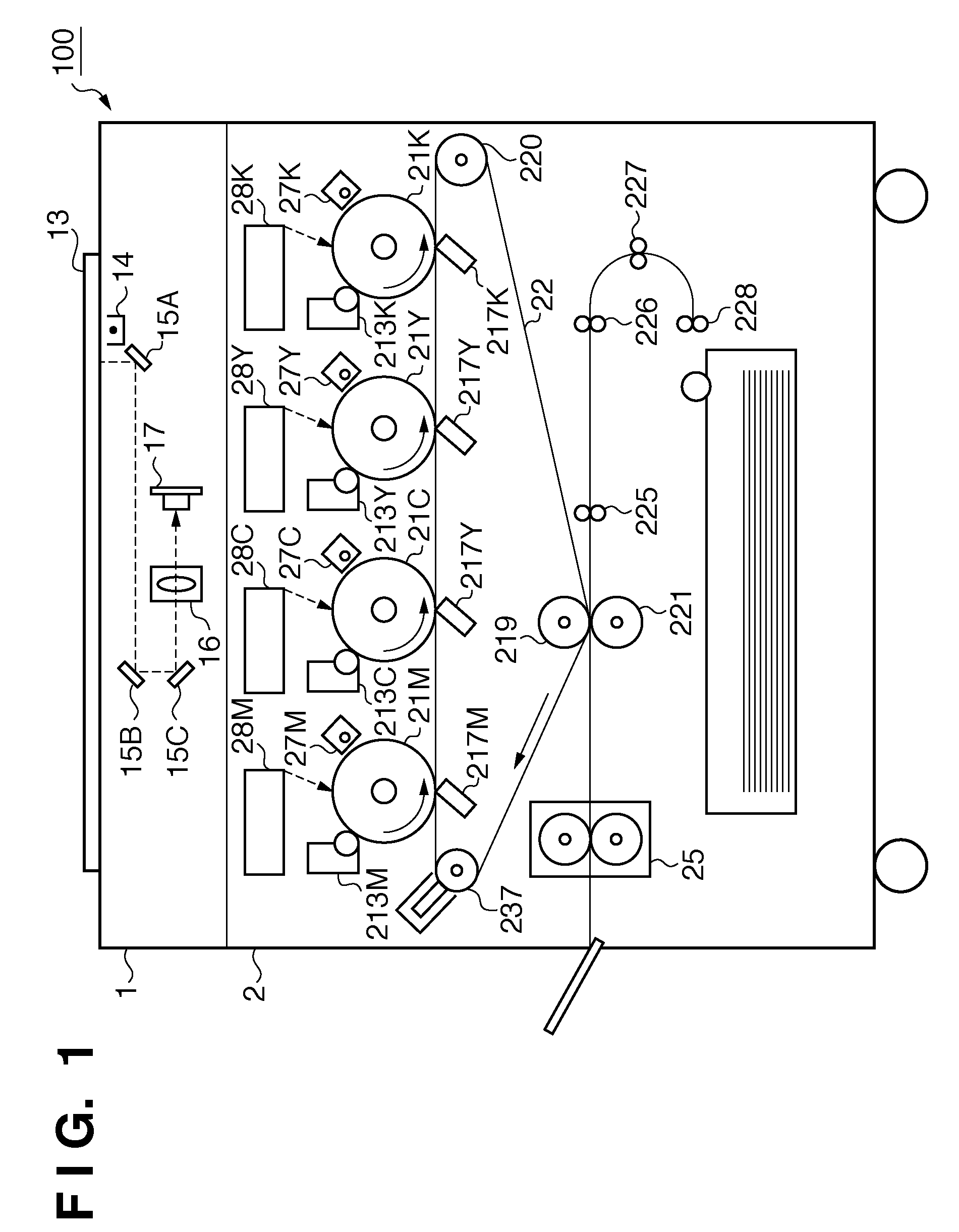
[0051]FIG. 1 is an outline cross-sectional view of an image forming apparatus in which a multicolor image is formed by superimposing a plurality of colors according to the present embodiment. This image forming apparatus is shown as a color copier having a four drum system in which four photosensitive members are arranged in tandem. It should be noted that the image forming apparatus may be also realized as a printing apparatus, a printer, a multi-function peripheral, or a facsimile machine for example. Furthermore, it is sufficient for the number of colors to be two or more. Accordingly, it is also sufficient for there to be two or more ph...
PUM
 Abstract
Description
Claims
Application Information