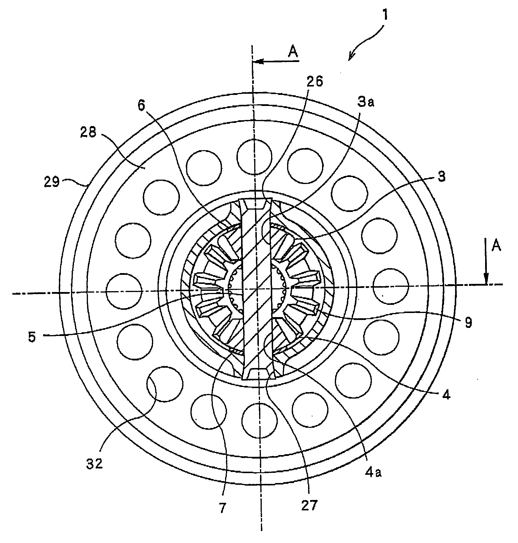
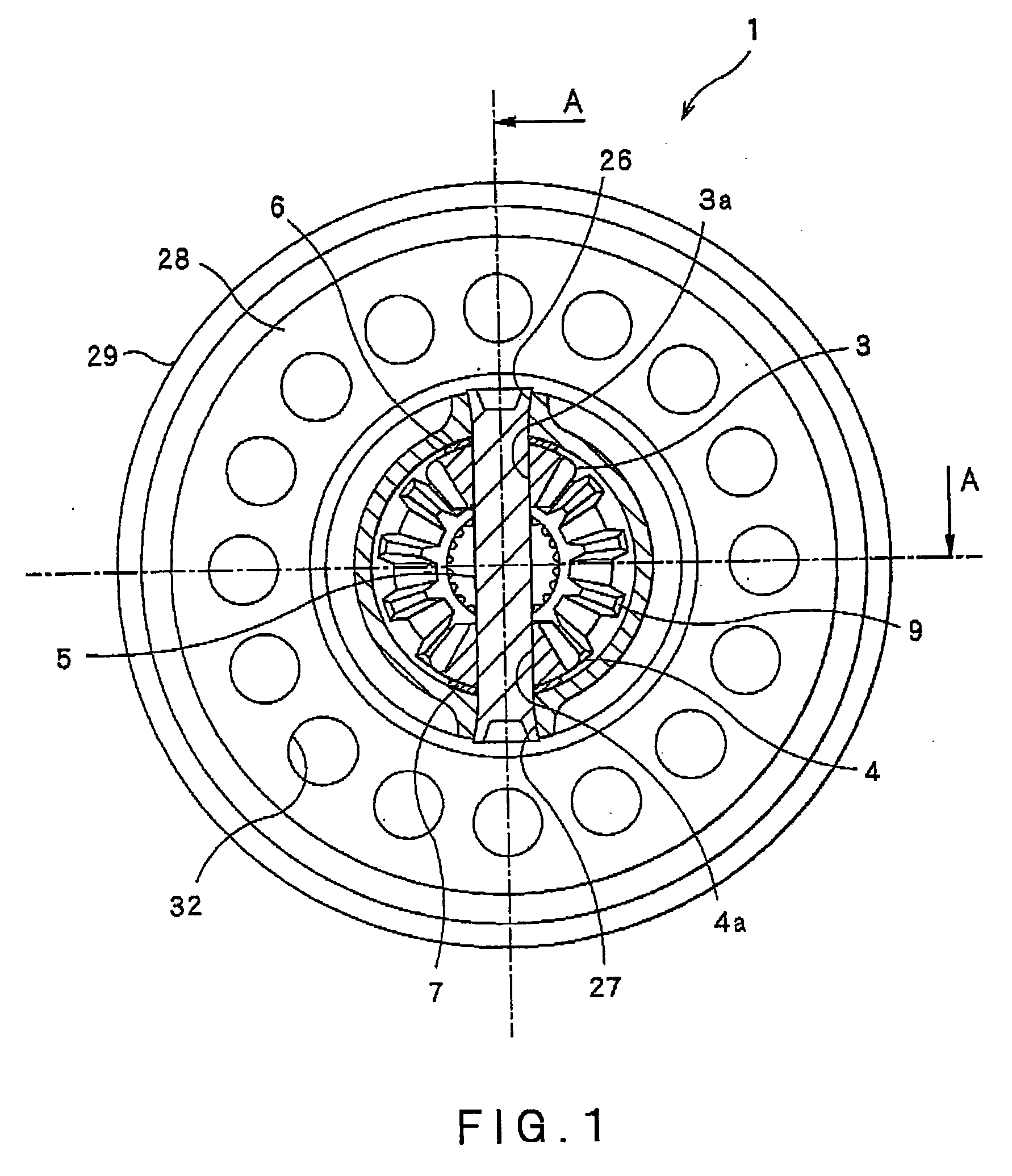
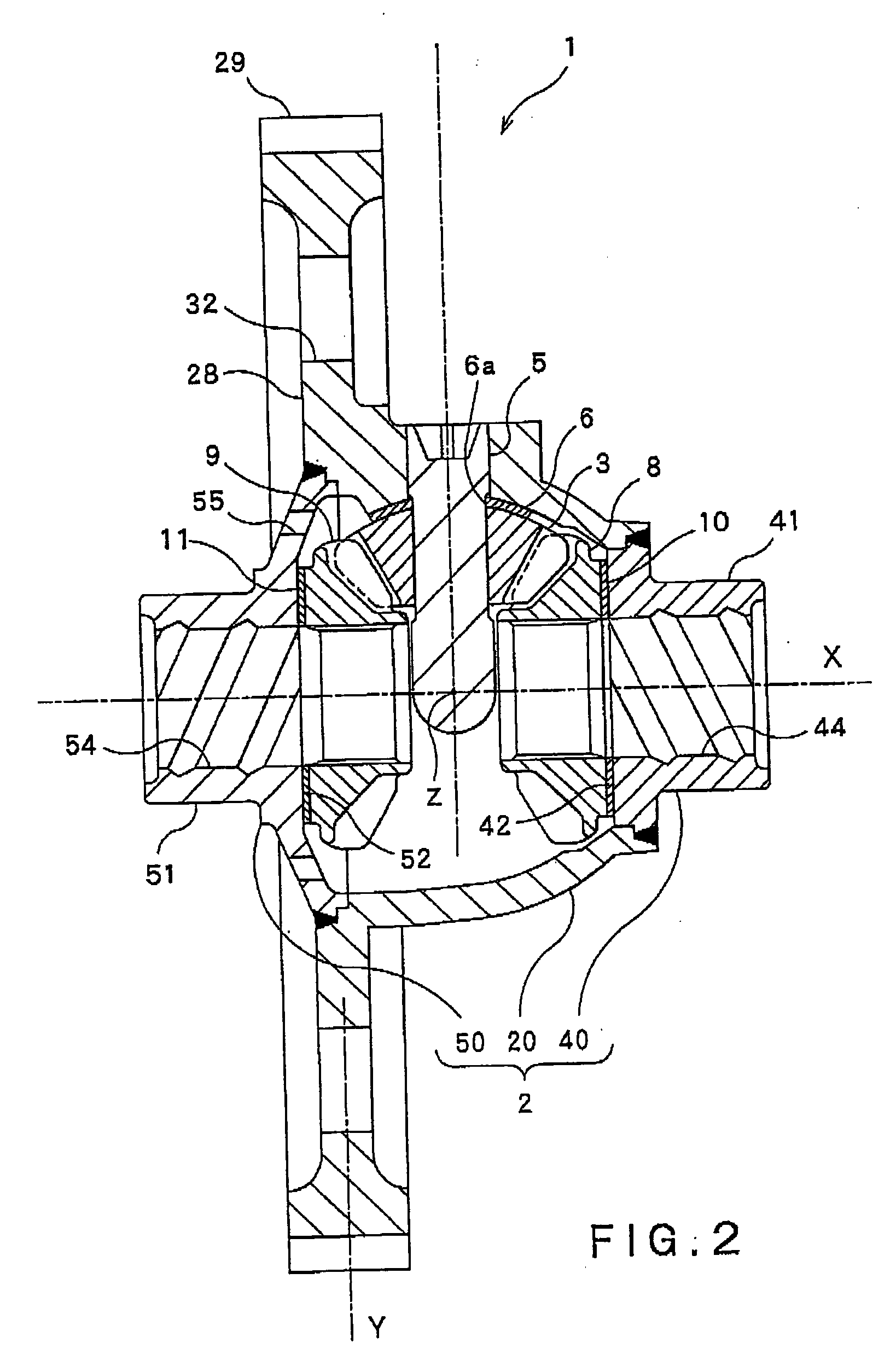
[0019]The present invention has been made in order to solve the above problems. The object of the present invention is to provide a differential gear having the following advantageous features. Namely, the differential gear has a desired durability, but has a light weight structure because no bolt is used for fastening a differential case and a ring gear to each other. Since no bolt is used, the number of components can be decreased, whereby costs can be decreased. In addition, since an axial size of an element to be forged is reduced, forging of the element can be facilitated. Another object of the present invention is to provide a method for manufacturing such a differential gear.
[0021]According to the present invention, since it is not necessary for the differential case and the ring gear to be fastened to each other by means of bolts, the thickness of the differential case can be reduced, whereby the weight of the differential case can be decreased. Further, since the number of components (bolts) can be decreased, costs can be also decreased. Furthermore, the first case body extending from the pinions-shaft assembling parts to the part of the ring gear (including the ring gear) is integrally formed by forging. Namely, since the welded part between the first case body and the second case body, and the welded part between the first case body and the third case body, are located away from a
torque transmission area (area between the pinion-shaft assembling parts and the ring gear), the
welding parts of lower strength can be prevented from being damaged when a torque is transmitted.
[0022]In addition, the first case body extending from the pinion-shaft assembling parts to the ring gear, the second case body having the first boss part, and the third case body having the second boss part, are formed separately from each other by forging. Namely, the axial lengths of the respective case bodies are shorter than that of a conventional differential case element. Thus, forging of the respective case bodies can be facilitated.
[0024]In this case, due to the
quenching process, the strengths of the
flange part and the ring gear can be improved. During the
quenching process, the surface of the
flange part is shrunk by a heat generated by the
quenching process. However, since the
flange part has a shape which is formed symmetrically with respect to the vertical surface that is positioned at the center of and is perpendicular to the
axial length of the toothed profile of the ring gear, the shrinkage on the one axial end side of the flange part and the shrinkage on the other axial end side thereof are substantially the same. Thus, a radial dimensional deviation in the axial direction of the toothed profile of the ring gear can be effectively restrained.
[0026]In this case, due to the
nitriding process, a hardened layer of, e.g.,
iron nitride, is formed on the inner circumferential surfaces of the first boss part and the second boss part, whereby the durability thereof can be improved. In addition, due to the quenching process, the strengths of the flange part and the ring gear can be improved. In particular, the inner circumferential surfaces of the first boss part and the second boss part are subjected to the
nitriding process, before the first case body and the second case body are welded to each other, and before the first case body and the third case body are welded to each other. Thus, the flange part and the ring gear of the first case body whose strengths have been improved by the quenching process (which is performed before the
welding process) can be prevented from being annealed by a heat generated during the
nitriding process. Accordingly, the strengths of the flange part and the ring gear can be effectively prevented from being lowered.
[0028]In this case, when the other-end-side outer circumferential surface of the second case body is pressed into the one-side-end inner circumferential surface of the first case body, the one-end-side inner circumferential surface in parallel with the axis line of the first case body and the other-end-side inner circumferential surface in parallel with the axis line of the second case body are brought into contact to each other. Thus, the axis center of the first case body and the axis center of the second case body can be aligned with each other. In addition, when the one-end-side outer circumferential surface of the third case body is pressed into the other-end-side inner circumferential surface of the first case body, the other-end-side inner circumferential surface in parallel with the axis line of the first case body and the one-end-side outer circumferential surface in parallel with the axis line of the third case body are brought into contact with each other. Thus, the axis center of the first case body and the axis center of the third case body can be aligned with each other. Namely, there can be easily formed the differential case in which the axis center of the first case body, the axis center of the second case body, and the axis center of the third case body are aligned with each other. As a result, the differential gear including the differential case of great precision can be provided.


