Conformable vascular prosthesis delivery system

a delivery system and vascular technology, applied in the field of catheter-based delivery systems, can solve problems such as increased vessel injury, and achieve the effects of less local trauma, less traumatic, and reduced radial for

Inactive Publication Date: 2009-08-27
BLISSLIGHTS LLC
View PDF0 Cites 17 Cited by
  • Summary
  • Abstract
  • Description
  • Claims
  • Application Information

AI Technical Summary

Benefits of technology

[0010]One embodiment involves a short balloon segment which is inflated at one end of the prosthesis and then pulled to traverse the length of the prosthesis, dilating the surrounding prosthesis and securing it to the vessel wall as it traverses the length of the prosthesis. The short balloon segment causes less local trauma to the vessel relative to a full length balloon.
[0011]Another embodiment involves use of a self-expandable mesh to expand the surrounding prosthesis and secure it to the vessel wall. The self expandable mesh is less traumatic than a typical angioplasty balloon because of the lower radial forces applied and the relatively higher transverse flexibility of the mesh.

Problems solved by technology

Not only does this require the use of two or more device interventions to achieve the desired outcome, but the nature of the self expanding stent allows for continued long-term expansion in the vessel even 7 to 9 months after implantation, resulting in increased vessel injury.
Although vulnerable plaques are non-stenotic or nominally stenotic, it is believed that their rupture, resulting in the release of thrombotic contents, accounts for a significant fraction of adverse cardiac events.

Method used


Image

  • Conformable vascular prosthesis delivery system
  • Conformable vascular prosthesis delivery system
  • Conformable vascular prosthesis delivery system

Examples


example 1

[0022]Example 1 illustrates a direct balloon pullback embodiment of the invention with reference to FIGS. 1-3.

[0023]A preferred embodiment includes a flexible catheter shaft similar to a common PTCA balloon or Balloon Expandable Stent Delivery System. The shaft has both a guide wire lumen and an inflation lumen. The inflation lumen is in fluid connection with the inside of a small balloon near the distal end of the catheter, as in similar catheters commonly utilized in catheter labs. The balloon is collapsed or folded into a low profile segment for delivery. A vascular prosthesis or stent is loaded into position with its distal edge covering the central portion of the balloon segment, with the remaining length trailing off proximal to the balloon directly adjacent with the shaft. Radio-opaque marker bands may be provided at varying locations along the distal portion of the catheter shaft to allow the interventionalist to predict the initial and final expanded length of the prosthesi...

example 2

[0029]Example 2 illustrates a balloon-in-a-balloon pullback embodiment of the invention with reference to FIGS. 4-5.

[0030]This example illustrates an alternative embodiment to that of Example 1. Similar in function, this embodiment utilizes an expandable sleeve, which may be a secondary “balloon” which houses the smaller dilation balloon inside. This outer balloon is longer, residing beneath the full length of the prosthesis. FIG. 5 shows this configuration without the prosthesis in place. The outer balloon provides an expandable sleeve which permits facile sliding of the dilation balloon within it, but will not transmit the pull force from the dilation balloon to the prosthesis, thereby enabling a more controlled delivery and expansion. This outer balloon may be compliant or non-compliant. An alternate embodiment utilizes a secondary inflation lumen for filling this second balloon, for providing lubrication between the balloons and possibly to aid in collapsing the entire structure...

example 3

[0031]Example 3 illustrates a captive prosthesis with balloon pullback embodiment of the invention with reference to FIGS. 6-16.

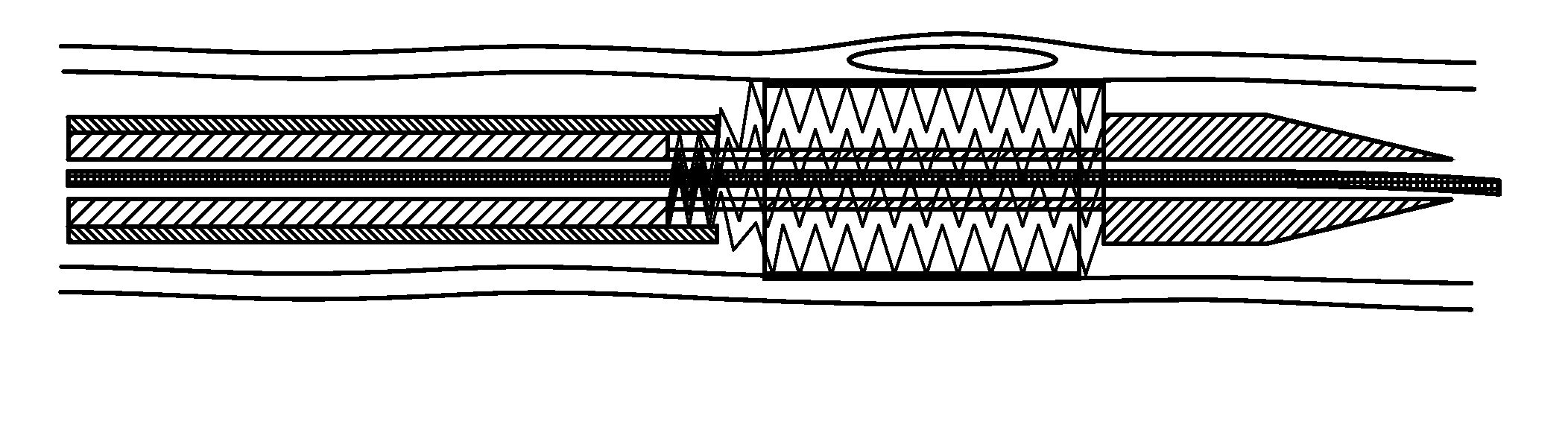
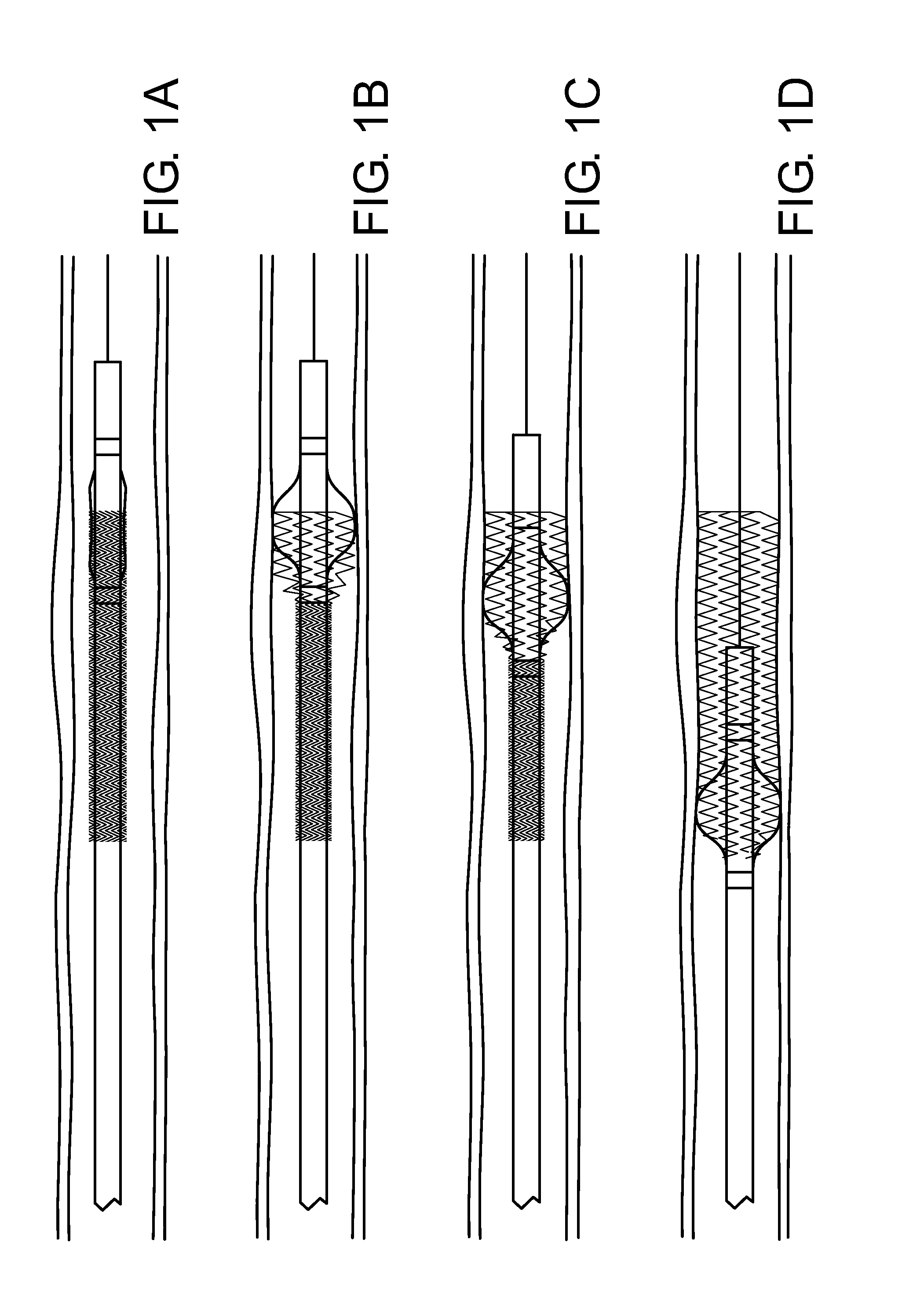
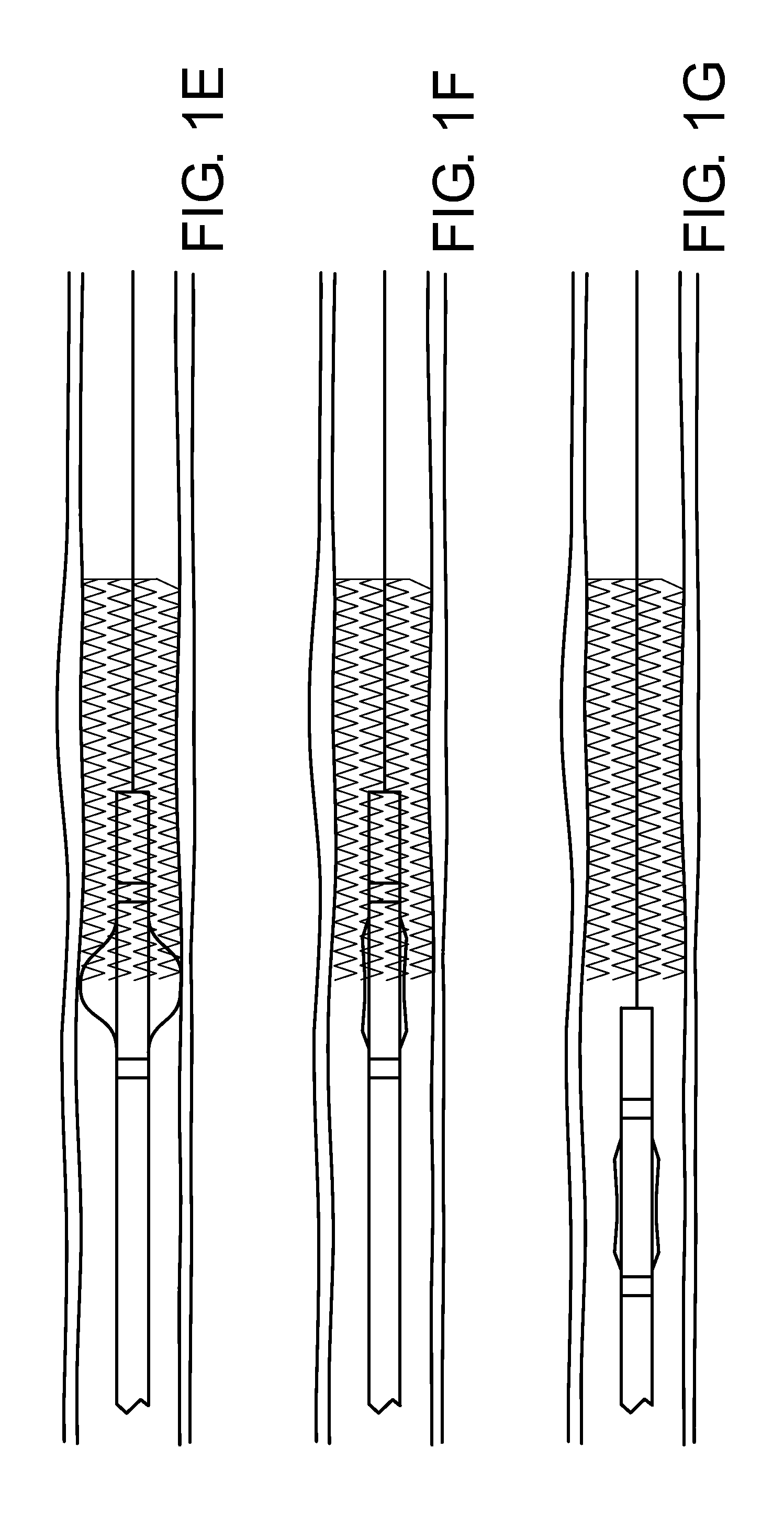
[0032]This alternate embodiment is similar to that of Example 1, with the addition of a thin sleeve over the prosthesis to protect it during delivery. As the balloon is expanded and drawn back, the flexible prosthesis is pulled from between the inner catheter shaft and outer sheath and expanded over the balloon into position at the vessel wall. FIGS. 6(a) thru (g) illustrate the sequential operation of this embodiment in section view. FIGS. 7 and 8 show an enlarged view to reveal the details of these same sequences. FIGS. 9-12 are detailed views with arrows indicating each component. FIG. 13 shows sequential isometric views of the prosthesis deployment within a sectioned vessel. FIGS. 14-16 show this same sequence with a full color representation and partially transparent balloon and prosthesis.


PUM


Abstract

Novel approaches for a conformable vascular prosthesis delivery system are provided which overcome the limitations of existing high pressure balloons for delivering intravascular prostheses to the site of high-risk plaques. One embodiment involves a short balloon segment which is inflated at one end of the prosthesis and then pulled to traverse the length of the prosthesis, dilating the surrounding prosthesis and securing it to the vessel wall as it traverses the length of the prosthesis. The short balloon segment causes less local trauma to the vessel relative to a full length balloon. Another embodiment involves use of a self-expandable mesh to expand the surrounding prosthesis and secure it to the vessel wall. The self expandable mesh is less traumatic than a typical angioplasty balloon because of the lower radial forces applied and the relatively higher transverse flexibility of the mesh.

Description

[0001]This application claims the benefit of U.S. provisional patent application Ser. No. 60 / 785,577 filed Mar. 24, 2006, which is incorporated by reference herein in its entirety.FIELD OF THE INVENTION[0002]The invention relates generally to the field of catheter-based delivery systems for endoluminal vascular prostheses.BACKGROUND OF INVENTION[0003]Vascular stents are commonly used today for percutaneous transluminal angioplasty (PTA) that involve the delivery and deployment of a self expandable or balloon expandable stent to create a scaffolding for both improving and maintaining patency in diseased or otherwise constricted vessels.[0004]Self-Expanding (SE) stents are typically constructed from Stainless Steel or Nitinol, either from laser cut and electro-polished tubing or welded wire braids, coils or other wire mesh forms that allow for a small unexpanded profile to reach distal lesions in tortuous vessels which can be deployed and expanded in place when released from a captive...

Claims


Application Information

Patent Timeline
Patent Type & Authority Applications(United States)
IPC IPC(8): A61F2/84
CPCA61M25/0119A61F2/958
Inventor GRANADA, JUANFURNISH, SIMON M.
Owner BLISSLIGHTS LLC
Why Eureka
Try Eureka