

Water Discharger
- Summary
- Abstract
- Description
- Claims
- Application Information
AI Technical Summary
Benefits of technology
Problems solved by technology
Method used
Image

Examples
first embodiment
[0138]As the invention, a water discharger having a control means including a magnet and a leaf spring in combination is described.
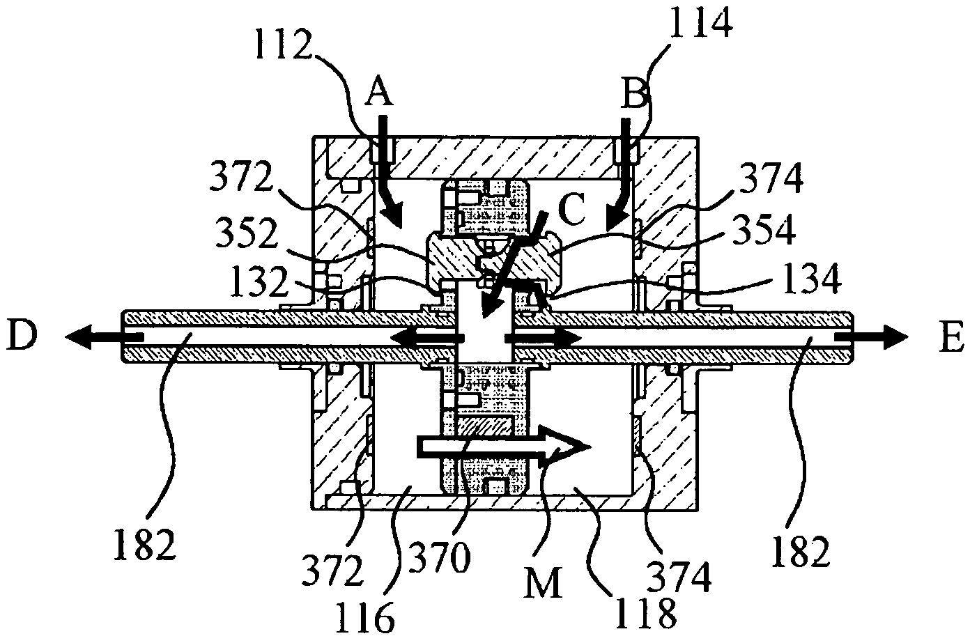
[0139]FIGS. 8 to 11 are schematic views showing the relevant part of a water discharger of the first embodiment of the invention. More specifically, FIG. 8 is a perspective view of the water discharger of this embodiment, FIG. 9 is a perspective cutaway view thereof, FIG. 10 is a cross section, and FIG. 11 is a cross section along line 11-11 in FIG. 10. Water discharger 100 of this embodiment has water discharge tubular body 180 that illustratively protrudes from both sides of the housing formed from housing main body 102 and housing lid 104. Water discharge tubular body 180 has a hollow structure having water discharge channel 182 inside and opened at the tip. Water discharge tubular body 180 does not necessarily need to be shaped as a circular cylinder, but various other examples may be contemplated including a rectangular cylinder and a flattened shap...
second embodiment
[0176]Next, as the invention, a water discharger having a control means including a magnet and a leaf spring in combination for reciprocating rotary motion is described.
[0177]FIGS. 15 to 18 are schematic views showing the relevant part of a water discharger according to the second embodiment of the invention. More specifically, FIG. 15 is a perspective view of the water discharger of this embodiment, FIG. 16 is a perspective cutaway view thereof, FIG. 17 is a vertical cross section, and FIG. 18 is a cross section along line 18-18 in FIG. 17.
[0178]Water discharger 200 of this embodiment has water discharge tubular body 280 that illustratively protrudes on one side from a housing formed from housing main body 202 and housing lids 203, 204. Water discharge tubular body 280 has a hollow structure having water discharge channel 282 inside and opened at the tip. When fluid such as water is introduced into water inlet ports 212, 214 provided in housing main body 202, water discharge tubula...
fourth embodiment
[0205]Next, as a third and fourth embodiment of the invention, water dischargers having a control means including a leaf spring and a slide bar in combination are described.
PUM
 Abstract
Description
Claims
Application Information