Linear Light Source Device, and Image Reading Device and Planar Display Device Using the Linear Light Source Device

a light source device and linear technology, applied in the field of linear light source devices, can solve the problems of high cost of power supply circuits, complicated correction circuits, and poor environment of cold cathode tubes

Active Publication Date: 2009-09-03
ROHM CO LTD
View PDF19 Cites 34 Cited by
  • Summary
  • Abstract
  • Description
  • Claims
  • Application Information

AI Technical Summary

Benefits of technology

[0030]In a preferred embodiment, in the circumferential surface of the main body, the predetermined range in the circumferential direction within which the recesses or the projections are to be formed to be spaced from each other in the longitudinal direction of the main body corresponds to a central angle of 3 to 45°, and more preferably 5 to 30° of the main body....

Problems solved by technology

However, the use of a cold-cathode tube as the linear light source device of a CCD image sensor unit U has drawbacks as follows.
Firstly, to drive a cold-cathode tube, a high voltage for discharge generated by using e.g. an inverter is necessary, so that the cost for the power supply circuit is high.
Secondly, a cold-cathode tube is not good for environment, because mercury vapor, which is harmful, is enclosed.
Although such a reduction in the light receiving amount can ...

Method used


Image

  • Linear Light Source Device, and Image Reading Device and Planar Display Device Using the Linear Light Source Device
  • Linear Light Source Device, and Image Reading Device and Planar Display Device Using the Linear Light Source Device
  • Linear Light Source Device, and Image Reading Device and Planar Display Device Using the Linear Light Source Device

Examples


first embodiment

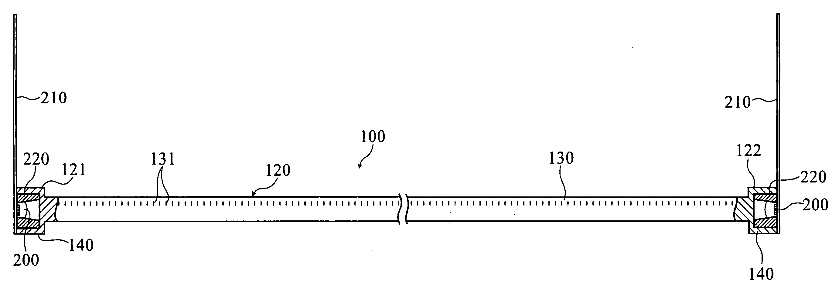
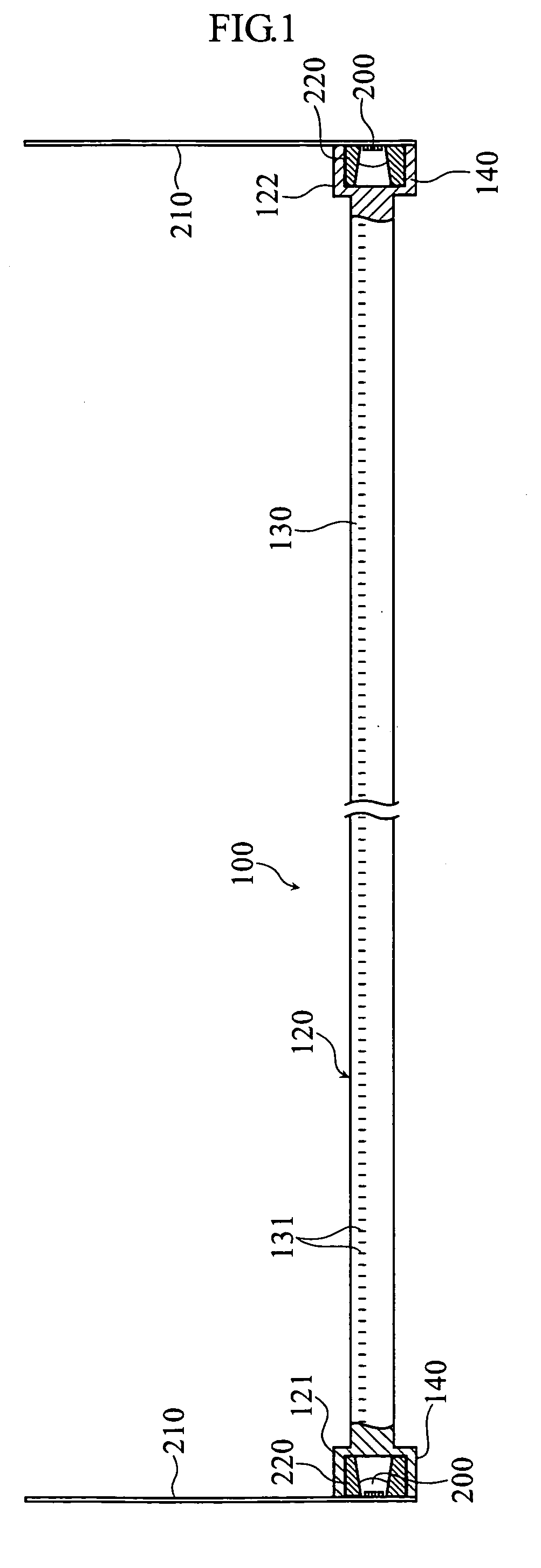
[0061]FIGS. 1-5 show a linear light source device 100 according to the present invention. The linear light source device 100 includes a light guide member 120 and LED elements 200 arranged at the two ends of the light guide member 120.

[0062]As shown in FIG. 1, the light guide member 120 includes a main body 130 in the form of a column having a uniform circular cross section throughout the length, and a first end 121 and a second end 122 provided at the two ends of the main body 130. The light guide member 120 is made of e.g. a transparent resin such as PMMA or polycarbonate or other transparent materials such as transparent glass to be an integral part. For instance, the columnar main body 130 has a length corresponding to the reading range of A4 size and has a diameter of about 3 mm. At least the circumferential surface of the main body 130 is a smooth mirror surface.

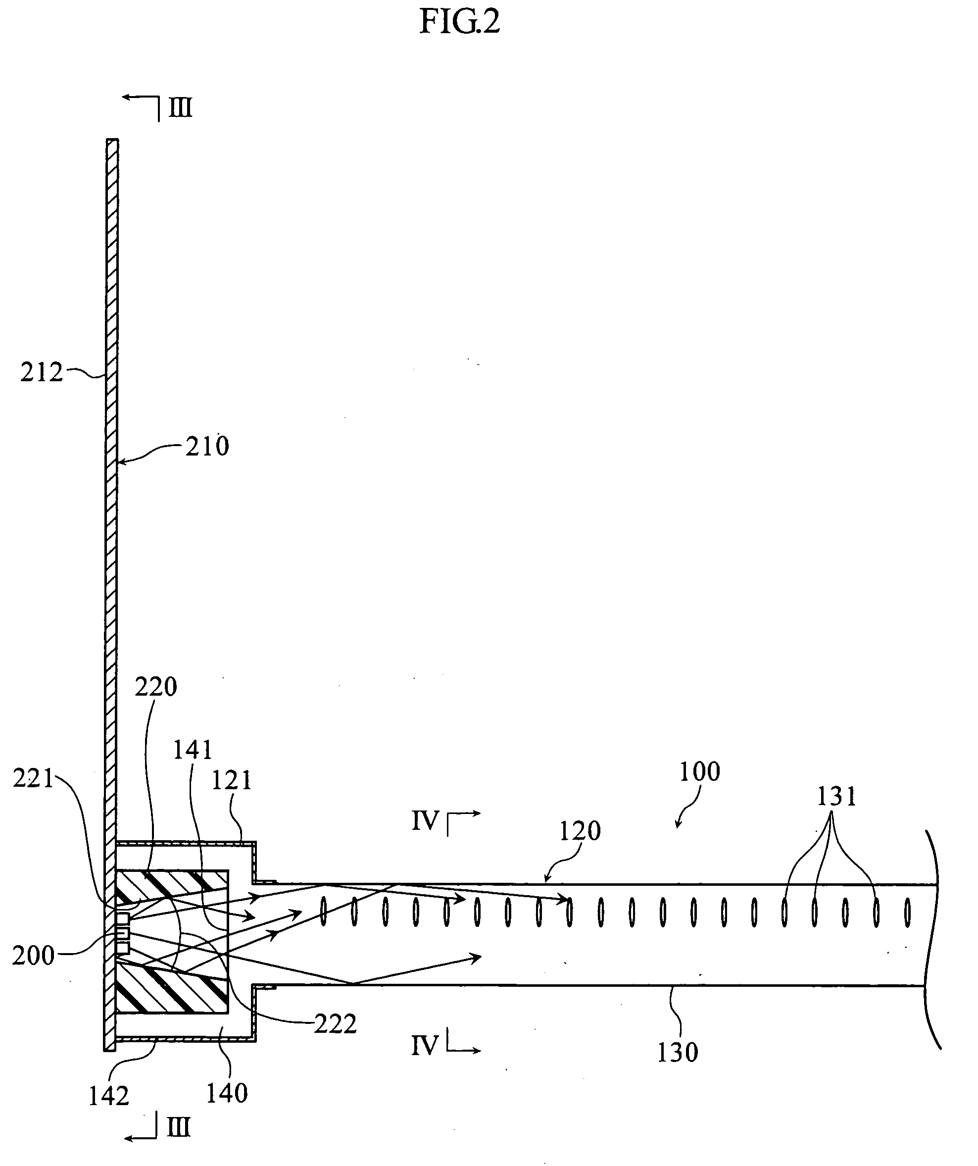
[0063]As will be understood from FIGS. 4 and 5, the main body 130 is formed, at a predetermined surface region in th...

third embodiment

[0092]As shown in FIG. 15, a backlight (illuminator) of a flat display apparatus 400 such as a liquid crystal display apparatus can be provided by arranging a plurality of linear light source devices 100B of the third embodiment side by side. Specifically, the linear light source devices 100B are arranged at predetermined intervals on the rear side of a flat display panel 410 so that the light emitted from each main body 130 is directed toward the reverse surface of the flat-display panel 410.

[0093]As noted before, since the light emission range of the linear light source device 100B is relatively large, the light source device illuminates a region in the form of a wide strip, although it is a linear light source device. Thus, by arranging the plurality of light source devices side by side so that the strip-like regions are connected to each other, the flat display panel 410 is illuminated from behind with a uniform amount of light regardless of the size of the flat display panel. P...


PUM


Abstract

A light guide member (120) includes a columnar main body (130) of a predetermined length, which is made of a transparent material and has a substantially uniform cross section. A first end (121) and a second end are provided at respective ends of the main body (130), and LED elements (200) are arranged to face the first end (121) and the second, respectively. The main body(130) includes a smooth mirror circumferential surface formed with a plurality of recesses (131) or projections spaced from each other in the longitudinal direction and arranged within a predetermined range in the circumferential direction. Due to the recesses or projections, throughout the length of the main body (130) , light emitted from the LED elements (200) and introduced into the main body (130) through each of the first end (121) and the second end is emitted from a region of the circumferential surface of the main body (130) which faces the range formed with the recesses (131) or the projections.

Description

TECHNICAL FIELD[0001]The present invention relates to a linear light source device, while also relating to an image reader and a flat display apparatus using a linear light source device. Particularly, the present invention relates to a linear light source device which is suitably used as an illumination light source of an image reader such as an image scanner or used as a backlight of a flat display apparatus such as a liquid crystal display apparatus.BACKGROUND ART[0002]A flat-bed image scanner is disclosed in e.g. Patent Document 1. The image scanner utilizes an image sensor unit U in which a CCD line sensor is mounted. (Hereinafter, this unit is referred to as a “CCD image sensor unit”). As shown in FIG. 11 of the present application, such a CCD image sensor unit U generally includes an illumination light source 1, a plurality of mirrors 21-25, a lens 3 and a CCD line sensor 4 which are housed in a case 5. In the flat-bed image scanner S, the CCD image sensor unit U is moved in ...

Claims


Application Information

Patent Timeline
IPC IPC(8): H04N1/04F21V8/00F21V29/00H01L33/58H01L33/60H01L33/62
CPCG02B6/001G02B6/0038H01L2924/12041H01L2924/00014H01L2924/01006H01L2924/01047H01L2224/45H01L24/45H04N1/02895G02B6/0068G03B27/54H01L33/58H04N1/02815H04N1/02835H04N1/0284H01L2924/00H01L2224/48H01L2924/00011H01L24/48H01L2224/45099H01L2224/43H01L33/00
Inventor FUJIMOTO, HISAYOSHINAGAHATA, TAKAYA
Owner ROHM CO LTD
Why Eureka
Try Eureka