Method and apparatus for enhanced resolution microscopy of living biological nanostructures

a biological nanostructure and enhanced resolution technology, applied in the field of imaging, can solve the problems of limited spatial resolution of such far-field microscopy, inability to resolve conventional light microscopy, and damage to the photon surface,

Inactive Publication Date: 2009-09-03
BAYLOR COLLEGE OF MEDICINE +1
View PDF2 Cites 76 Cited by
  • Summary
  • Abstract
  • Description
  • Claims
  • Application Information

AI Technical Summary

Problems solved by technology

The spatial resolution of such far-field microscopy is limited by the smallest possible size of a light spot produced by the focusing optics.
However, many subcellular structures of high research interest, such as mitochondria, endoplasmic reticulum, microtubules, and vesicles, have often sizes that are below this physical limit and thus cannot be resolved with conventional light microscopy.
Although there exist imaging techniques of significantly higher resolution than light microscopy, most of them require conditions that are hostile to living specimen, e.g., the high vacuum environment of electron microscopy.
Both techniques employ high-intensity point of illumination and thus may suffer from photo damage, which is a drawback for both approaches.
In addition, STED instrumentation is highly cost intensive.
2007)], resulting in low imaging speed insufficient for real-time imaging.

Method used


Image

  • Method and apparatus for enhanced resolution microscopy of living biological nanostructures
  • Method and apparatus for enhanced resolution microscopy of living biological nanostructures
  • Method and apparatus for enhanced resolution microscopy of living biological nanostructures

Examples


example 1

1D SWM—Imaging of 100 nm Diameter Fluorescent Beads

[0091]The resolution of the SW-TIRFM system was tested by imaging fluorescent beads with a known diameter of 100 nm, which is below the resolution limit of standard microscopy.

[0092]Beads suspended in water were delivered to a polylysine coated coverslip, which caused a portion of the beads to adhere to the coating. Utilizing TIR illumination improved the axial selection, which resulted in images of high contrast, with very bright beads adjacent to the glass / water interface and a dark background undisturbed by non-adhered beads. Both TIRFM and reconstructed SW-TIRFM images of the same 100 nm bead are shown in FIG. 14A and FIG. 14B, respectively. The full width at half maximum (FWHM) of the intensity profile taken of the TIRFM image was 265 nm (FIG. 14D). The intensity profiles taken in two orthogonal directions, normal and parallel to the fringes of the reconstructed SWM image (FIG. 14E) had a FWHM of approximately 100 nm (x-profile...

example 2

1-D SWM—Biological Structures (Nanotubes)

[0094]SWM vas applied to image biological nanotubes, i.e., membrane tethers between living cells. The formation of such membrane tethers is a general phenomenon that occurs during cell adhesion, communication and spreading. Previously, direct measurement of tether diameters had not been possible with light microscopy, since they are considerably below the lateral resolution limit of conventional light microscopy. Scanning electron microscopy (SEM) measurements performed on fixed cells have suggested that tethers are 50-200 nm thick [Rustom, A., Saffrich, R., Markovich, I., Walther, P., and Gerdes, H. H., “Nanotubular highways for intercellular organelle transport,”Science 303(5660):1007-1010 (2004)].

[0095]An SWM setup was used to determine the diameter of membrane tethers that formed spontaneously between cultured human embryonic kidney (HEK) cells. These tethers stretch between interconnected cells and are up to several cell diameters in len...

example 3a

2-D SWM—Imaging of 100 nm Diameter Fluorescent Beads

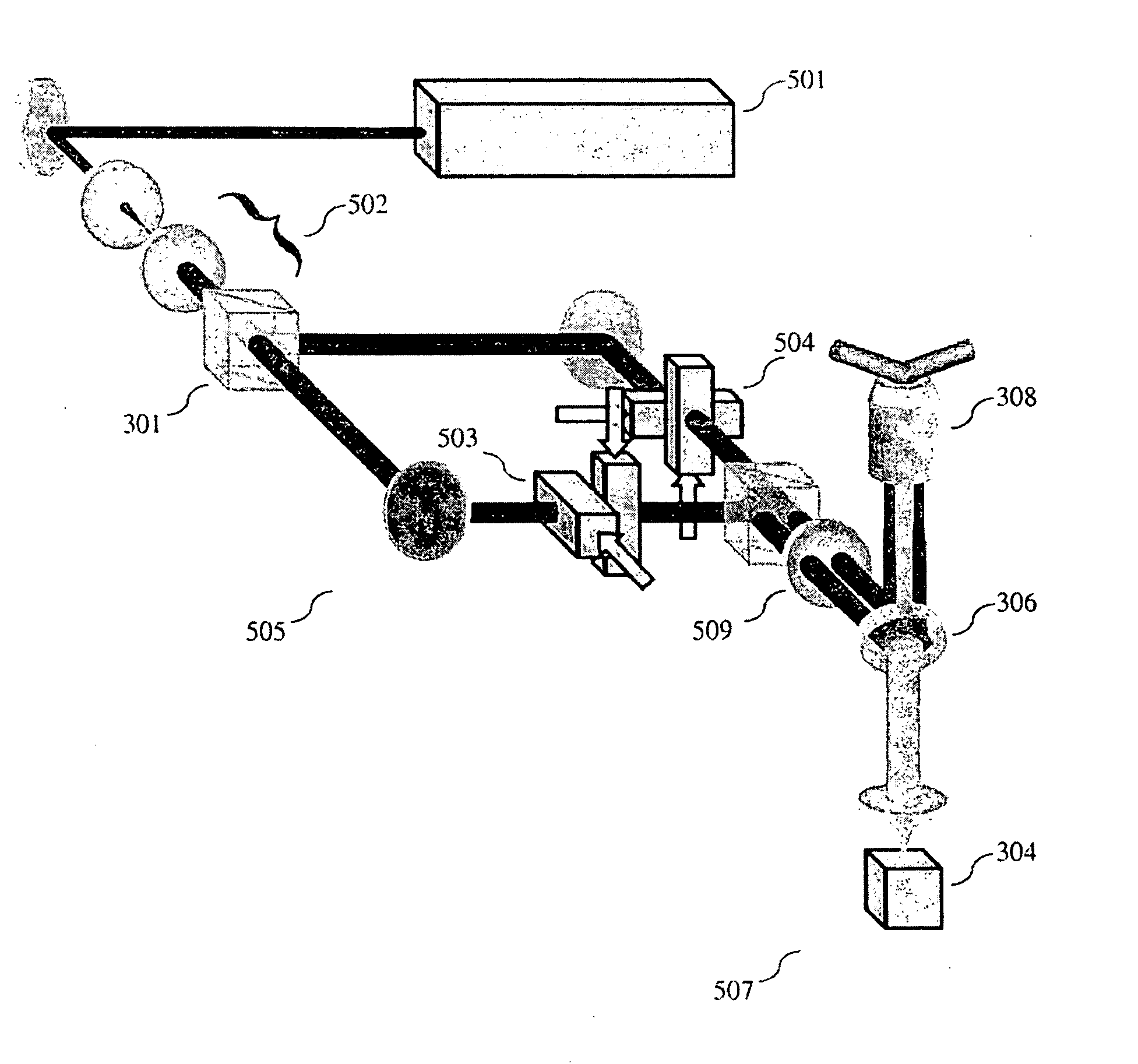
[0097]An image of the specimen illuminated by the SW was formed by utilizing the 2D SWFM illustrated in FIG. 5 and was enlarged and captured by the detector unit 507, which was a cooled CCD camera 304. To obtain 2D resolution enhancement, multiple images have to be acquired while the sub-resolution structure of interest is illuminated with SW patterns of different and angular orientations. Numerical simulations indicated that three different orientations of SW pattern about optical axis are sufficient to achieve a nearly isotropic effective PSF. [See Chung, et al. 2007]. Data involved acquiring a sequence of three images at three SW phases (0°, 120°, 240°) and angular orientation (0°, 60°, 120°), resulting in a total of nine images. Preliminary results of generating and controlling nine such SW patterns with AODs are illustrated in FIG. 16.

[0098]Despite the use of large (10 mm) aperture AODs, the total time to change between the ni...


PUM

PropertyMeasurementUnit
wavelengthaaaaaaaaaa
diameteraaaaaaaaaa
frequencyaaaaaaaaaa

Abstract

The present invention is a method and apparatus that utilizes an inertia-free diffraction mechanism to control both phase and rotation of the standing wave pattern that results in super-resolution at unparalleled imaging speeds. In some embodiments of the present inventions, AODs are utilized to control period, phase, and rotation of the SW pattern in contrast to the commonly used mechano-optical principles. This allows 2D (and 3D) super-resolution imagining at high stability and speed not limited by mechanical constraints. The present invention can be utilized, for example, for real time observations of dynamic processes in living cells.

Description

CROSS-REFERENCE TO RELATED PATENT APPLICATIONS[0001]This application claims priority to: provisional U.S. Patent Application Ser. No. 61 / 021,755, filed on Jan. 17, 2008, entitled “Method and Apparatus for Enhanced Resolution Microscopy of Living Biological Nanostructures,” which provisional patent application is commonly assigned to the assignee of the present invention and is hereby incorporated herein by reference in its entirety for all purposes.BACKGROUND[0002]1. Field of the Invention[0003]This invention relates generally to the field of imaging. More specifically, the invention relates to a method and apparatus for high speed, three-dimensional microscopy with enhanced resolution.[0004]2. Background of the Invention[0005]Real time observations of dynamic processes in living cells are of increasing importance in experimental biology and have inspired the development of various noninvasive imaging techniques. One example is fluorescence-based light microscopy (fluorescence micro...

Claims


Application Information

Patent Timeline
Patent Type & Authority Applications(United States)
IPC IPC(8): G02F1/33
CPCG02B21/06G02B21/0016
Inventor SAGGAU, PETERGLIKO, OLGAREDDY, GADDUM DUEMANI
Owner BAYLOR COLLEGE OF MEDICINE
Why Eureka
Try Eureka