
Lid member and electronic device using the same

Active Publication Date: 2009-09-03
PANASONIC INTELLECTUAL PROPERTY MANAGEMENT CO LTD
View PDF7 Cites 42 Cited by
  • Summary
  • Abstract
  • Description
  • Claims
  • Application Information

AI Technical Summary

Benefits of technology

[0009]The present invention addresses these problems, and provides a lid member that has a certain locking function having high environmental resistance against temperature / humidity variation or the like of an ambient environment and high dust proof performance, and an electronic device using the lid member.

Problems solved by technology

In such a structure, disadvantageously, a difference in expansion / contraction rate occurs between materials dependently on the ambient environment such as temperature variation and hence sufficient locking performance cannot be secured.
Uniform pressing force cannot be applied to the packing dependently on the layout of the locking claw, so that the essential function of the lid member, namely putting a lid, becomes insufficient, and the water proof and dust proof cannot be performed.
Also in a structure where the packing and the lid member are integrated and simultaneously moved and the lid member is locked to the case of the electronic device, the difference in expansion / contraction rate between the packing and the lid member is apt to cause degradation of the packing, disadvantageously.

Method used


Image

  • Lid member and electronic device using the same
  • Lid member and electronic device using the same
  • Lid member and electronic device using the same

Examples


first exemplary embodiment

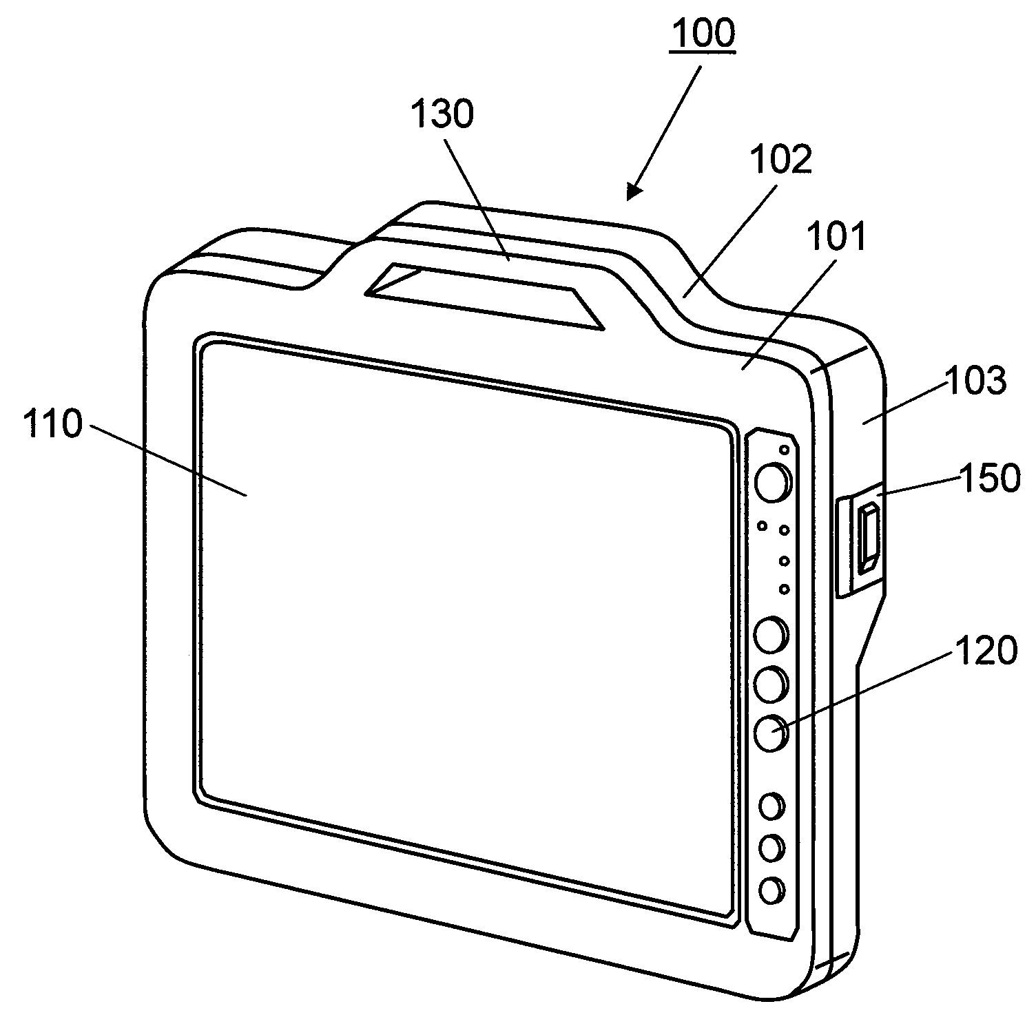
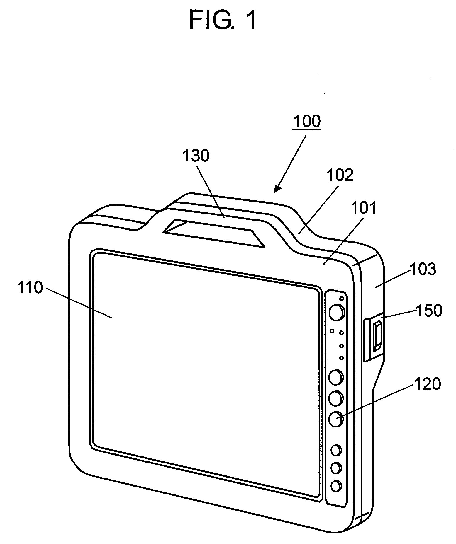
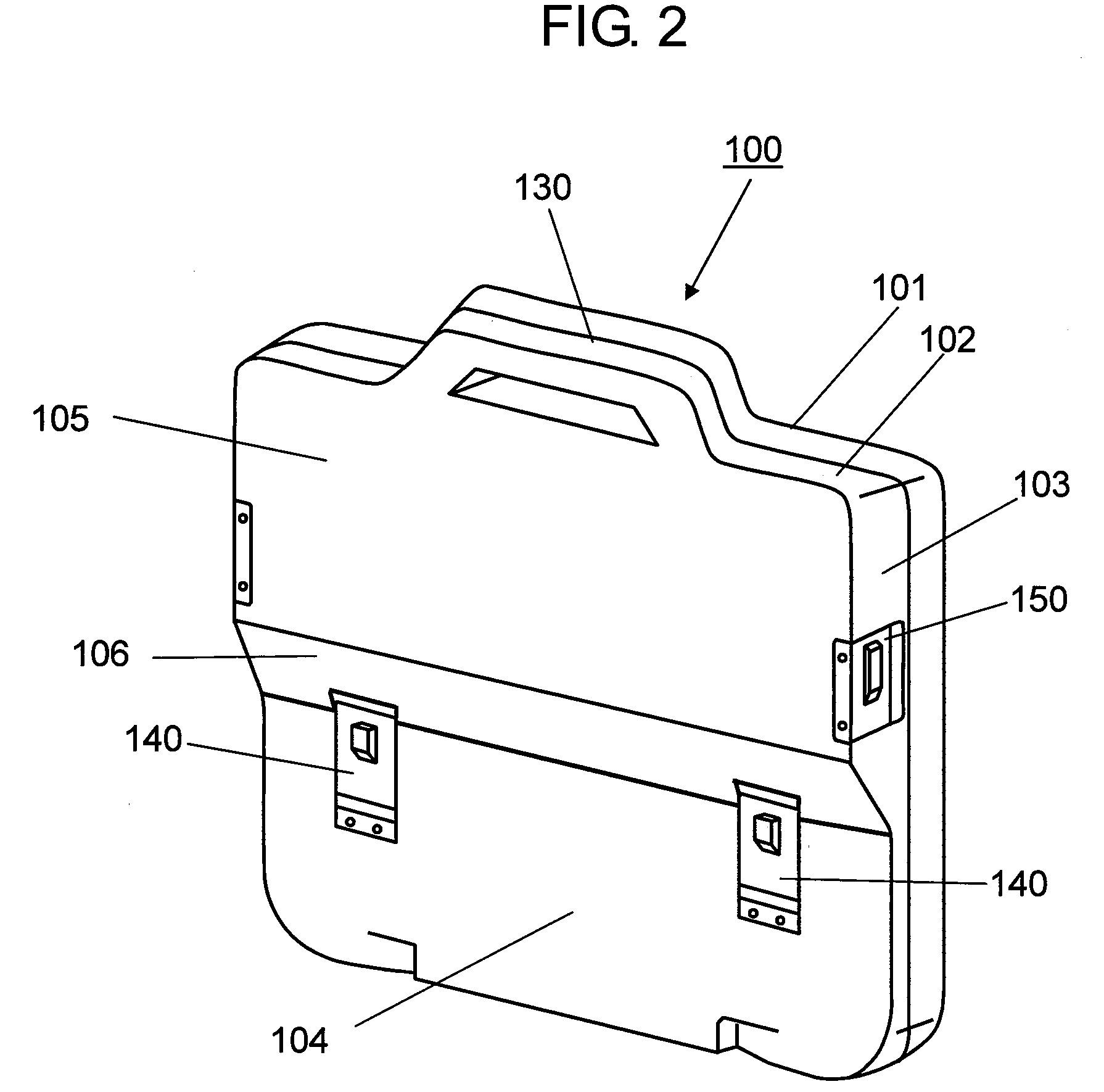
[0028]FIG. 1 is a perspective view from the front side of an electronic device in accordance with a first exemplary embodiment of the present invention. FIG. 2 is a perspective view from the back side of the electronic device. The electronic device in accordance with the first exemplary embodiment is an information terminal that has a display section as an indication section and an operation button on its front side. The electronic device is applied to a portable navigation system (NAVI), for example. In the present embodiment of the present invention, a NAVI is described as an example of the electronic device.

[0029]NAVI 100 has front case section 101 molded of resin or the like and back case section 102. As shown in FIG. 1, front case section 101 includes display section 110 such as a liquid crystal display as an indication section for displaying visible information, and operation button 120 as a control button for controlling the visible information by menu selection or the like o...

second exemplary embodiment

[0064]FIG. 8 is a perspective view showing a detail of lid member 700 in accordance with a second exemplary embodiment of the present invention. FIG. 9 is a perspective view showing a structure of storage section 202 in accordance with the second exemplary embodiment. As shown in FIG. 8, the basic structure of lid member 700 of the second exemplary embodiment is similar to that of the first exemplary embodiment in FIG. 4A and FIG. 4B. In the second exemplary embodiment, however, storage section 202 is disposed at the position of lid member 150 of FIG. 1 and FIG. 2, and the structure of lid latch 720 is different from that in the first exemplary embodiment.

[0065]In other words, as shown in FIG. 8, lid member 700 of the second exemplary embodiment has two projections 780a disposed on end surface section 780 of the sliding direction of lid latch 720, and second projections 770a are disposed on both end surface sections 770 orthogonal to the sliding direction of lid latch 720 with respe...

third exemplary embodiment

[0071]FIG. 10A, FIG. 10B, and FIG. 10C are perspective views showing lid member 150 and a structure of storage section 900 of NAVI 100 using it in accordance with a third exemplary embodiment of the present invention. FIG. 10A is a perspective view of lid member 150, FIG. 10B is a perspective view showing the structure of storage section 900, and FIG. 10C is a perspective view showing a state where a lid is put on storage section 900 by lid member 150.

[0072]Lid member 150 and storage section 900 of the third exemplary embodiment are appropriate when they are disposed astride thick section 105 and side section 103 of back case section 102 of NAVI 100 or when they are disposed astride thin section 104 and side section 103, especially as shown in FIG. 1 and FIG. 2. As the third exemplary embodiment of the present invention, however, lid member 150 disposed astride thick section 105 and side section 103 is described as an example. The storage section is appropriate to a connection termi...


PUM


Abstract

An electronic device has an opening in a case, a lid member that includes a first lid member having a pair of first engaging sections for putting a lid on the opening at its both ends, a second lid member that has a pair of second engaging sections engaging with the first engaging sections and slides on a main surface of the first lid member, and a projection disposed at an end of the sliding direction of the second lid member. The case has an engaging hole engaging with the projection disposed on the second lid member.

Description

BACKGROUND OF THE INVENTION[0001]1. Field of the Invention[0002]The present invention relates to a lid member for putting a lid on a battery storage section, a recording medium storage section, or an external connection terminal storage section of an electronic device such as a notebook computer, and to an electronic device using the lid member, especially relates to a lid member allowing certain water proof and dust proof and to an electronic device using the lid member.[0003]2. Background Art[0004]Recently, electronic devices having high portability have become widespread, and are used very often not only in doors but also out of doors. Therefore, the electronic devices have been demanded to have vibration resistance and impact resistance against carrying or fall and have environmental resistance against temperature / humidity variation of the ambient environment. Especially, even notebook computers have been more frequently used on the condition of a tough ambient environment such ...

Claims


Application Information

Patent Timeline
IPC IPC(8): H05K5/00H01M50/262H01M50/271
CPCH01M2/1022H05K5/0086H05K5/03H05K5/06H05K5/0239G06F1/1658Y02E60/10H01M50/262H01M50/271
Inventor MURAKATA, MASATO
Owner PANASONIC INTELLECTUAL PROPERTY MANAGEMENT CO LTD
Learn More