
Slider and manufacturing method thereof, head gimbal assembly, disk drive with same

a technology of sliding disc and manufacturing method, which is applied in the direction of maintaining the head carrier alignment, recording information storage, instruments, etc., can solve the problems of inability to control the etching direction, low production efficiency, and inability to maintain the airflow and easy peeling off of the edge portion, so as to reduce the manufacturing time, improve production efficiency, and reduce the floating variation

Active Publication Date: 2010-02-02
SAE MAGNETICS (HK) LTD
View PDF13 Cites 2 Cited by
  • Summary
  • Abstract
  • Description
  • Claims
  • Application Information

AI Technical Summary

Benefits of technology

[0014]Therefore, considering drawbacks of conventional technology, the invention provides an incline portion structural slider with very small variation of floating, and a slider manufacturing method capable of manufacturing high accurate and variation controllable incline portion.
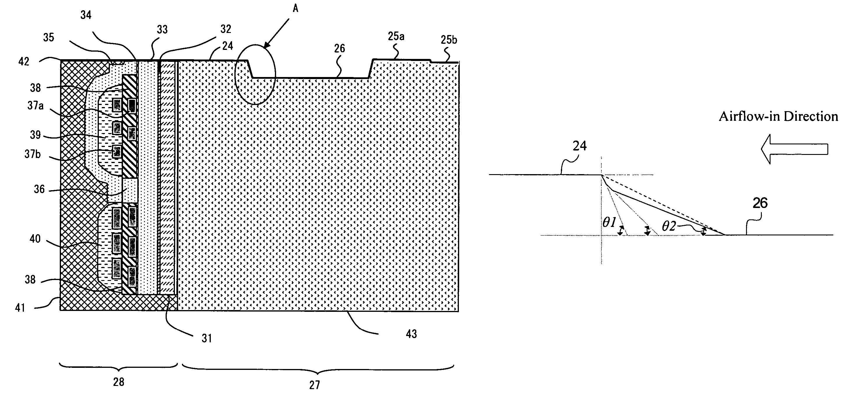
[0028]As illustrated above, according to the slider of the invention, the incline portion may be formed in a multi-segment structure by combining surfaces with two or more angles, thus providing a slider with an incline structure having small floating variation. In addition, according to the slider of the invention, the multi-segment may be formed by reactive ion etching method, thus enabling reduction of manufacture time and improvement of production efficiency.

Problems solved by technology

However, if the read / write portion is coupled to the concave portion with an angle of approximately 90 degree formed there between, that is, if the read / write portion is coupled with an edge portion of substantially right angle, turbulent airflow will be generated at position adjacent the wall of the edge portion, causing instable airflow and easy peeling off of the edge portion, both of which are undesirable.
In addition, when applied to ceramic of high hardness, etching rate will be very slow, thereby causing problems such as low production efficiency.
In addition, different from ion milling in which etching direction is determined by ion incidence angle, RIE belongs to chemical etching using reactive gases, therefore, etching direction control is impossible, adjustment of incline angle and formation of incline structure with specific shape is also difficult to realize.
In this period, depth of at least 10 nm is etched, and etching action in this unstable period becomes reason of variation, thus making it difficult to form the incline structure with fine precision.

Method used


Image

  • Slider and manufacturing method thereof, head gimbal assembly, disk drive with same
  • Slider and manufacturing method thereof, head gimbal assembly, disk drive with same
  • Slider and manufacturing method thereof, head gimbal assembly, disk drive with same

Examples


Embodiment Construction

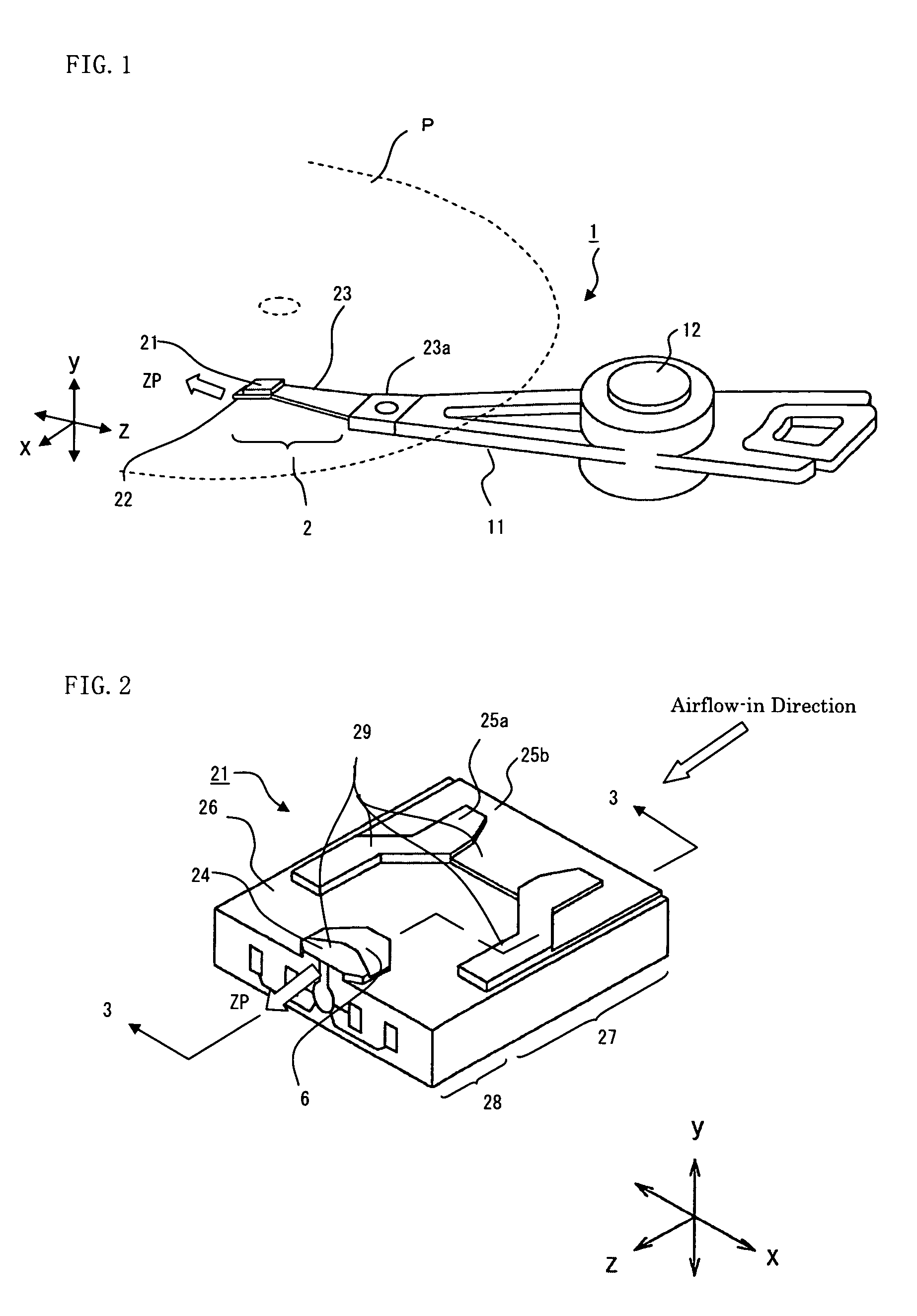
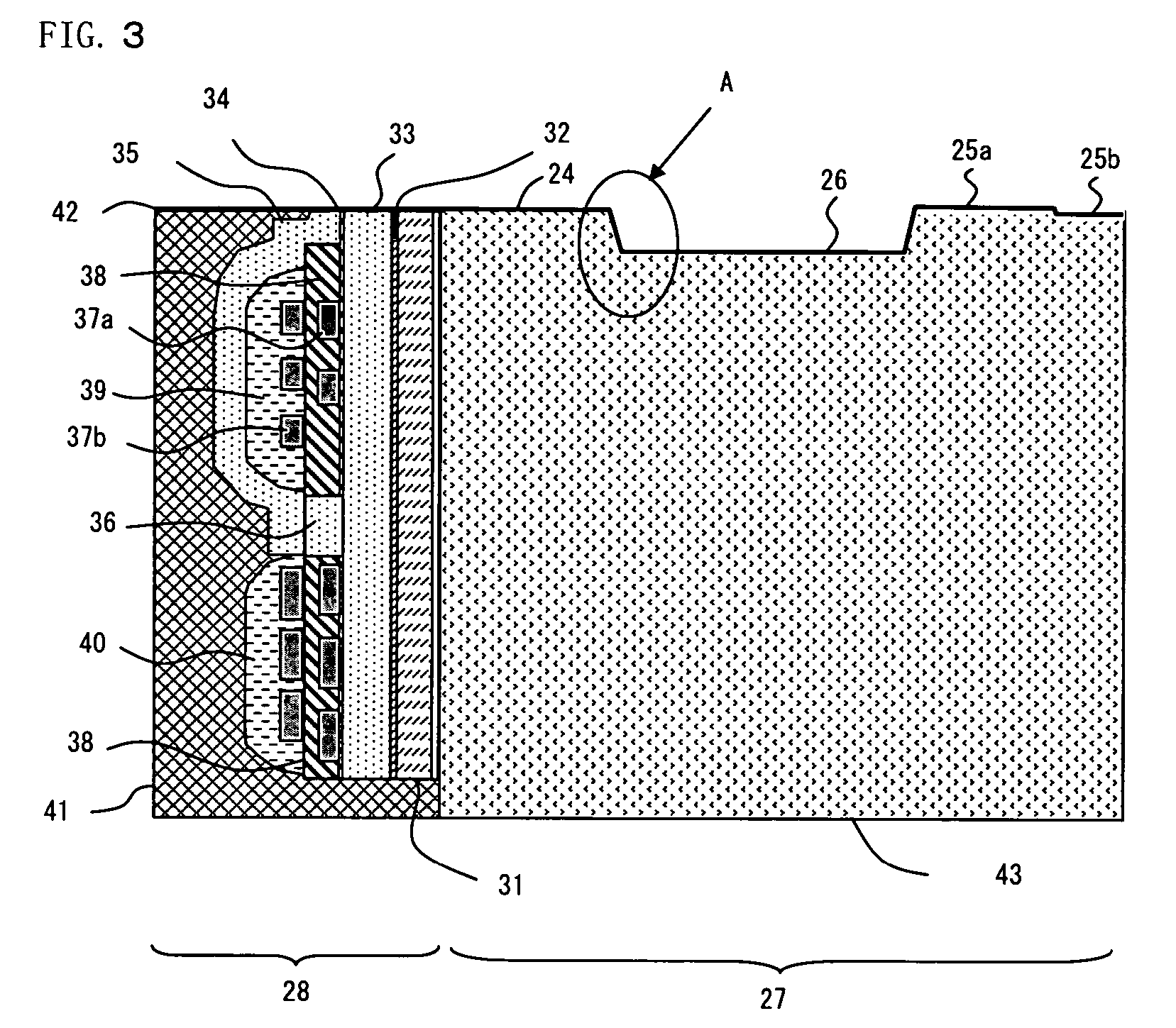
[0041]Embodiments of slider and manufacturing method thereof of the invention will now be described in detail in conjunction with the drawings. FIG. 1 shows a perspective view of a head arm assembly (HAA) with a slider provided on one distal end thereof. A plurality of head arm assemblies (HAAs) 1 of the same quantity as that of the disks are mounted in a hard disk drive (see FIG. 11). The head arm assembly 1 includes a drive arm 11 supported by a rotary shaft 12 at one end of the drive arm 11 and a head gimbal assembly (HGA) 2 disposed at distal end of the drive arm 11. The HGA 2 has a slider 21 with a thin film head portion 28 (see FIG. 11) formed thereon, a flexure 22 to support the slider 21 and a load beam 23 for connecting the flexure 22 to the drive arm 11. The HAA 1 rotates about the shaft 12 and positions the slider relative to recording medium P in accordance with certain position. Combination of the load beam 23 and a connection plate 23a that mounts the load beam 23 on t...


PUM

PropertyMeasurementUnit
angleaaaaaaaaaa
incline angleaaaaaaaaaa

Abstract

The invention discloses a manufacturing method of slider. The slider comprises an incline portion (6) connecting a read / write portion (24) disposed with a convex configuration on an air bearing surface opposite to a recording medium, and a concave portion (26) adjacent to an end thereof where airflow flows in. The incline portion (6) includes a first incline portion (61) with a substantially linear shape connected with a surface of the read / write portion (24) and a second incline portion (62) with substantially linear shape connected with the concave portion (26). A first incline angle θ1 of the concave portion (26) with respect to the first incline portion (61) is larger than a second incline angle θ2 of the concave portion (26) with respect to the second incline portion (62).

Description

FIELD OF THE INVENTION[0001]This application claims priority to Japanese Application No. 2005-091671, filed Mar. 28, 2005, and Chinese application No. 200510078489.5, filed Jun. 20, 2005. The entire contents of these applications are incorporated herein by reference.[0002]The present invention mainly relates to a slider for a disk drive and manufacturing method thereof.BACKGROUND OF THE INVENTION[0003]As a recording media of high speed, sufficient capacity, strong reliability and low cost, disk drives are widely used for digital information recording. With the development of technology for several years, recording density of a disk drive has been developed to exceed over 100 GB per square inch. A plurality of head arm assemblies each of which is comprised of a drive arm and a head gimbal assembly (HGA) disposed on distal end of the drive arm are provided in a disk drive, corresponding to number of disks which function as recording medium. The HGA includes a slider. The slider has a ...

Claims


Application Information

Patent Timeline
Patent Type & Authority Patents(United States)
IPC IPC(8): G11B21/21G11B5/60
CPCG11B5/6005G11B5/6082
Inventor HENG, CHENGBULI, GUOWEIHUANG, JIANHUI
Owner SAE MAGNETICS (HK) LTD
Learn More