Transmission system and a method for control thereof

Active Publication Date: 2009-09-03
ABB POWER GRIDS SWITZERLAND AG
View PDF7 Cites 34 Cited by
  • Summary
  • Abstract
  • Description
  • Claims
  • Application Information

AI Technical Summary

Benefits of technology

[0006]The object of the present invention is to provide a transmission system of the type defined in the introduction and a method for control thereof,

Problems solved by technology

It may cause large disturbances with very severe consequences on AC systems connected to a said HVDC transmission system if all the converters of a converter station and by that a converter station would fail and by that the power transmitted through the system falls to zero.
Such a starting procedure or stop procedure of converters for either increasing or reducing the voltage between said neutral bus and said pole has i

Method used


Image

  • Transmission system and a method for control thereof
  • Transmission system and a method for control thereof

Examples


Embodiment Construction

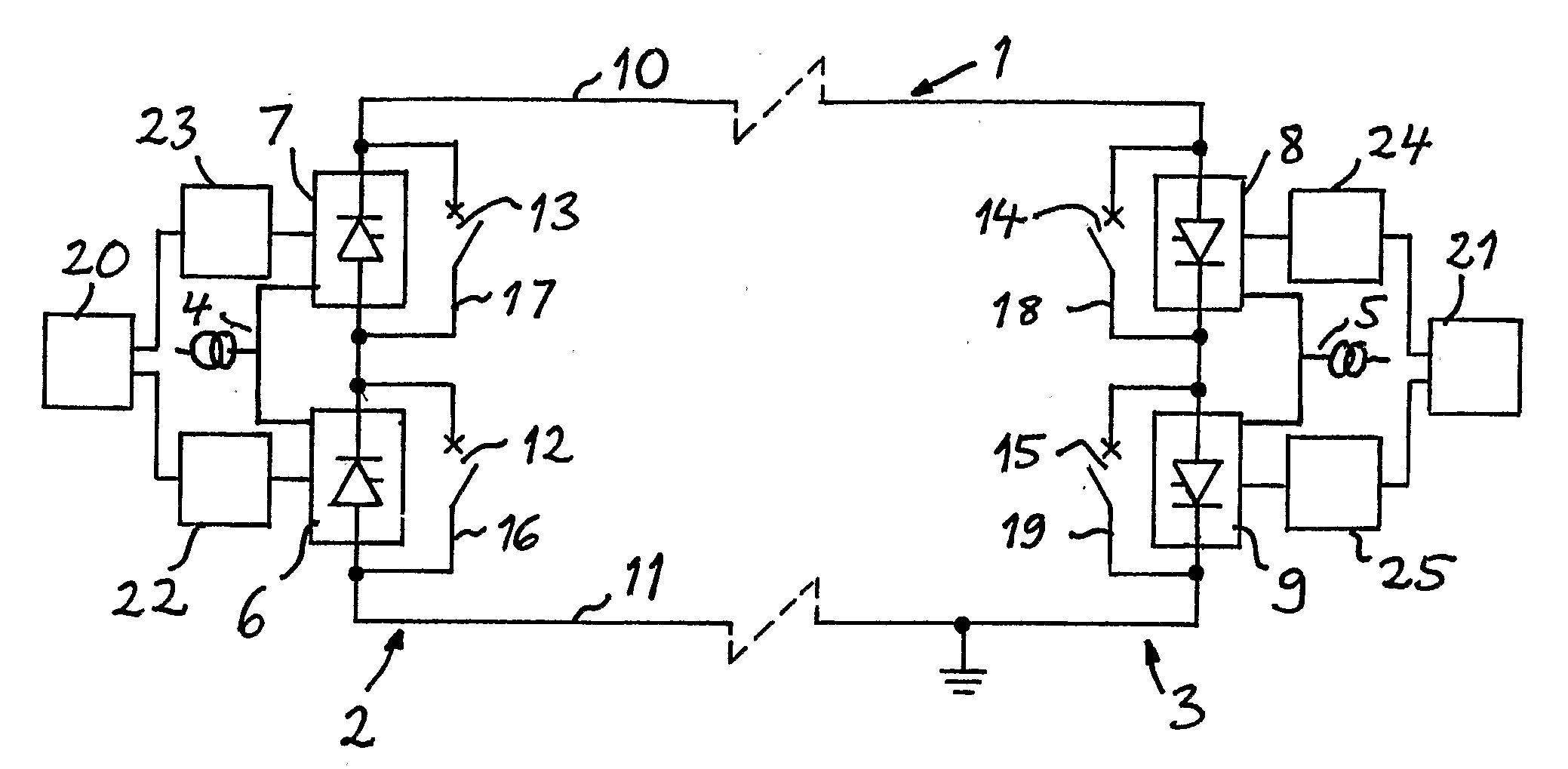
[0023]An HVDC transmission system according to a first embodiment of the invention is shown in FIG. 1. This system has here at each end of a transmission line 1 a converter station 2, 3 for connecting said transmission line to an AC system 4, 5 schematically indicated. The AC system 4 is assumed to be a generating system in the form of any type of power plant with generators of electricity, whereas the AC system 5 is assumed to be a consuming system or network connecting to consumers of electric power, such as industries and communities. Thus, a first converter station 2 is adapted to operate as rectifier and the other, second converter station 3 as inverter. Each station comprises a series connection of two converters 6, 7 and 8, 9 having a DC side thereof connected on one hand to a pole 10 of positive polarity of said transmission line on high potential and on the other to a neutral bus 11 on zero potential by being earthed. Each converter includes a number of converter valves in ...


PUM


Abstract

An HVDC transmission system including a rectifier station and an inverter station each having a series connection of at least two converters. A by-pass DC breaker is connected in parallel with each converter. A control device is adapted to deblock a blocked converter by starting to control the converter at high delay angle and gradually decreasing the delay angle until substantially all DC current flows through the converter and to then control the by-pass breaker to open at substantially zero current, and to stop the operation of a converter by controlling the converter at gradually increasing delay angle until the voltage across the converter is substantially zero and to then control the converter to be blocked by firing a by-pass pair thereof and to then control the by-pass breaker to close for taking over all the DC current when the voltage between a neutral bus and a pole of a transmission line between the stations is to be increased and reduced, respectively.

Description

TECHNICAL FIELD OF THE INVENTION AND PRIOR ART[0001]The present invention relates to a HVDC (High Voltage Direct Current) transmission system comprising at each end of an HVDC transmission line a converter station for connecting said transmission line to an AC system, each said station comprising a series connection of at least two converters having a DC side thereof connected on one hand to a pole of said transmission line on high potential and on the other to a neutral bus on zero potential by being earthed, a first of said converter stations being adapted to operate as rectifier and the other, second as inverter, each converter having a by-pass DC breaker connected in parallel therewith in a current path forming a by-pass of said converter when said breaker is closed, each converter station comprising an arrangement adapted to control the DC current through said pole and for each converter of the station a device for controlling that converter and the current therethrough for eit...

Claims


Application Information

Patent Timeline
IPC IPC(8): H02J3/36
CPCH02J3/36Y02E60/60H02M7/7575
Inventor BJORKLUND, HANSLUNGQVIST, ROLF
Owner ABB POWER GRIDS SWITZERLAND AG
Why Eureka
Try Eureka