Reflection-type mask and method of making the reflection-type mask

a mask and reflection technology, applied in the field of reflection masks, can solve the problems of increased shadowing effect, increased shadowing effect, increased intensity of light radiated from the photoabsorber layer to the outside of the mask,

Active Publication Date: 2009-09-03
KIOXIA CORP
View PDF2 Cites 75 Cited by
  • Summary
  • Abstract
  • Description
  • Claims
  • Application Information

AI Technical Summary

Problems solved by technology

However, there is a problem that if the film thickness of the pattern formed on the mask is increased, the influence of the shadowing effect is increased.
The shadowing effect is known as a problem with lithography using a reflection-type mask.
A problem then newly arises which relates to the shading performance of a region with which shading is to be performed, e.g., a shading frame.
There is a problem that if the film thickness of the photoabsorber layer is reduced in order to reduce the above-described shadowing effect, the intensity of light radiated from the photoabsorber layer to the outside of the mask is increased and a failure to ensure the desired shading performance of the shading frame results.

Method used


Image

  • Reflection-type mask and method of making the reflection-type mask
  • Reflection-type mask and method of making the reflection-type mask
  • Reflection-type mask and method of making the reflection-type mask

Examples


first embodiment

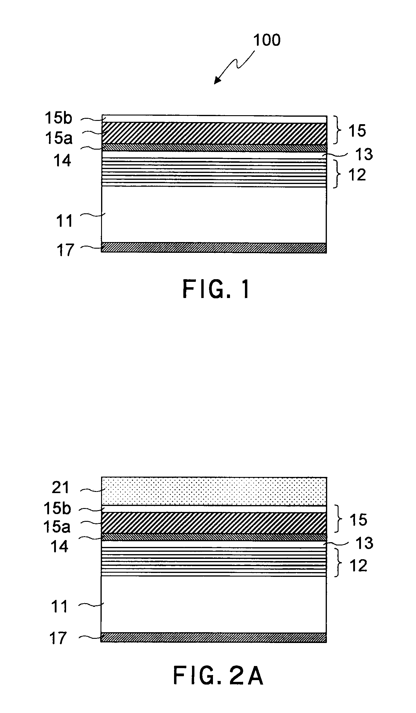
[0043]A method of making a mask blank used in making of a reflection-type mask according to the first embodiment of the present invention and components will be described. FIG. 1 is a sectional view of a mask blank 100.

[0044]As can be understood from FIG. 1, the mask blank 100 is made by successively forming a multilayer reflective film 12, a capping layer 13, a buffer layer 14 and a photoabsorber layer 15 on a glass substrate 11 and thereafter forming a back conductive film 17 on a back surface of the glass substrate 11. Each constituent member will be described below.

[0045]The glass substrate 11 is a glass substrate having an extremely low thermal expansion coefficient (a low thermal expansion material (LTEM)).

[0046]The multilayer reflective film 12 is a stack of a pair of thin films formed of molybdenum (Mo) thin film and silicon (Si) thin film in 40 to 50 pairs. This pair of films is formed by sputtering. The multilayer reflective film 12 reflects EUV light, which is exposure li...

second embodiment

[0064]The second embodiment of the present invention will be described. In the second embodiment, a mask blank 110 shown in FIG. 4 is used. This mask blank 110 differs from the mask blank 100 described above in the description of the first embodiment in that an electroconductive layer 19 is formed between the glass substrate 11 and the multilayer reflective film 12. The electroconductive layer 19 is a metal film having tantalum (Ta) or chromium (Cr).

[0065]A method of making a reflection-type mask 210 according to the present embodiment will be described.

(1) The process described above in the description of the first embodiment is performed on the mask blank 110 to obtain a reflection-type mask at an intermediate making stage shown in FIG. 5A.

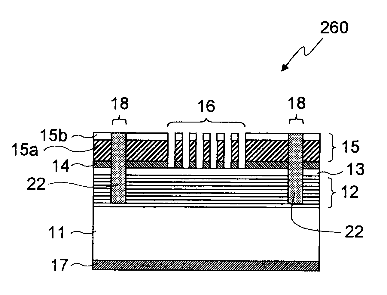
(2) Next, a plasma etching process for etching on the photoabsorber layer 15, the buffer layer 14, the capping layer 13 and the multilayer reflective film 12 is performed, as described above with respect to the first embodiment. However, as can ...

third embodiment

[0071]The third embodiment of the present invention will be described. In the third embodiment, a mask blank 120 shown in FIG. 6 is used. This mask blank 120 differs from the mask blank 100 described above in the description of the first embodiment in that, as can be understood from FIG. 6, a second photoabsorber layer 15-2 is formed on a first photoabsorber layer 15-1 corresponding to the photoabsorber layer 15 described above in the description of the first embodiment.

[0072]Each of the first photoabsorber layer 15-1 and the second photoabsorber layer 15-2 has an absorber 15a and an antireflection film 15b formed on the absorber 15a. A material containing tantalum (e.g., TaN, TaBN or TaBO) is used as the material of the photoabsorber layer.

[0073]The material and the film thickness of the first photoabsorber layer 15-1 are determined to enable attenuated phase shift exposure, as in the case of the photoabsorber layer 15 described in the description of the first embodiment.

[0074]A pr...


PUM

PropertyMeasurementUnit
wavelengthaaaaaaaaaa
angleaaaaaaaaaa
wavelengthaaaaaaaaaa

Abstract

To provide a reflection-type mask having a reduced shadowing effect, capable of phase shift exposure and having a shading frame of sufficient shading performance. The mask includes a substrate 11, a multilayer reflective film 12 which is formed above the substrate 11, and which reflects exposure light, a first photoabsorber layer 15 which is formed above the multilayer reflective film 12, and which absorbs the exposure light, a circuit pattern region 16 constituted, in conformity with a predetermined circuit pattern, of an opening formed as a result of removal of the first photoabsorber layer 15 and an absorbing portion where the first photoabsorber layer remains, and a shading region 18 having a reflectance with respect to the exposure light lower than that in the absorbing portion of the circuit pattern region 16.

Description

CROSS REFERENCE TO RELATED APPLICATION[0001]This application is based upon and claims the benefit of priority from the prior Japanese Patent Application No. 2008-052198, filed on Mar. 3, 2008, the entire contents of which are incorporated herein by reference.BACKGROUND OF THE INVENTION[0002]1. Field of the Invention[0003]The present invention relates to a reflection-type mask, e.g., one used in extreme ultraviolet (EUV) lithography and to a method of making the reflection-type mask.[0004]2. Background Art[0005]In recent years, EUV lithography using extreme ultraviolet having a wavelength in the vicinity of 13.5 nm as exposure light has been proposed to realize transfer of finer patterns.[0006]In EUV lithography, a reflection-type mask is used for reasons including small differences in absorptivity between materials to EUV light. A reflection-type mask used in EUV lithography is made on the basis of a substrate called a mask blank.[0007]The mask blank has a mutlilayer reflective film...

Claims


Application Information

Patent Timeline
Patent Type & Authority Applications(United States)
IPC IPC(8): G03F1/00G03F1/22G03F1/24H01L21/027
CPCB82Y10/00G03F1/26G03F1/24B82Y40/00
Inventor TAKAI, KOSUKE
Owner KIOXIA CORP
Why Eureka
Try Eureka