Apparatus and method

a technology of tubing and handling apparatus, which is applied in the direction of fluid removal, projectors, cameras, etc., can solve the problems of tubing bending or sag, the relationship between the deck space required and the arrangement, and the tubing may tend to bend or sag., so as to reduce the fatigue on the tubing and avoid plastic deformation

Inactive Publication Date: 2009-09-10
QSERV
View PDF15 Cites 8 Cited by
  • Summary
  • Abstract
  • Description
  • Claims
  • Application Information

AI Technical Summary

Benefits of technology

[0017]Controlling the rate of injection of tubing through the second injector head on the derrick to be the same as the rate of tubing drawn off the reel means that the length of the tubing between the main derrick injector head and the reel is maintained substantially constant, and the bend radius can thus ...

Problems solved by technology

This has drawbacks in relation to the deck space required.
However, this arrangement can be problematic since the lazy loop of tubing may tend to bend repeatedly due to the cyclical relative motion between the platform and the injector head.
In tho...

Method used


Image

  • Apparatus and method
  • Apparatus and method
  • Apparatus and method

Examples


Embodiment Construction

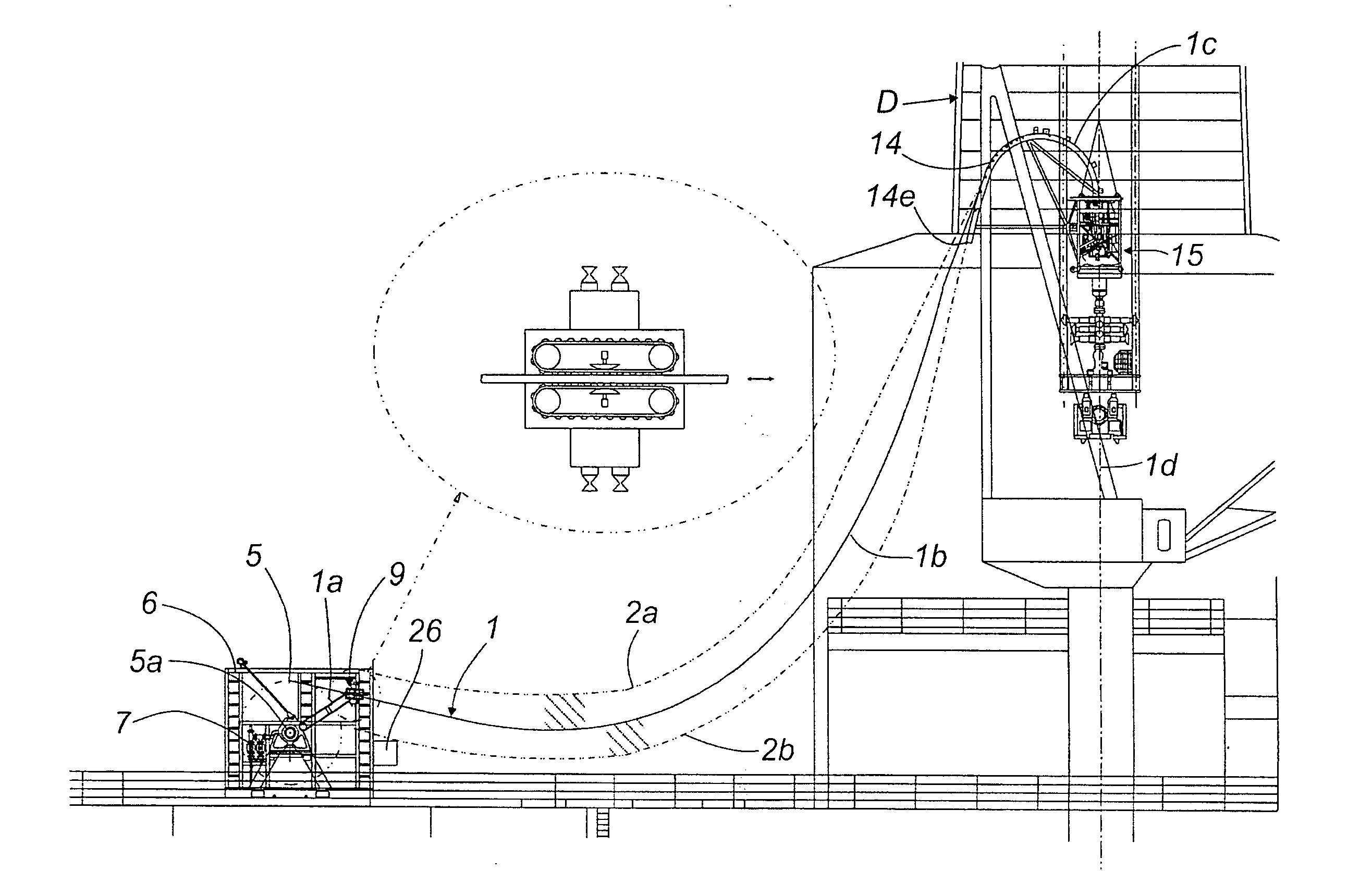
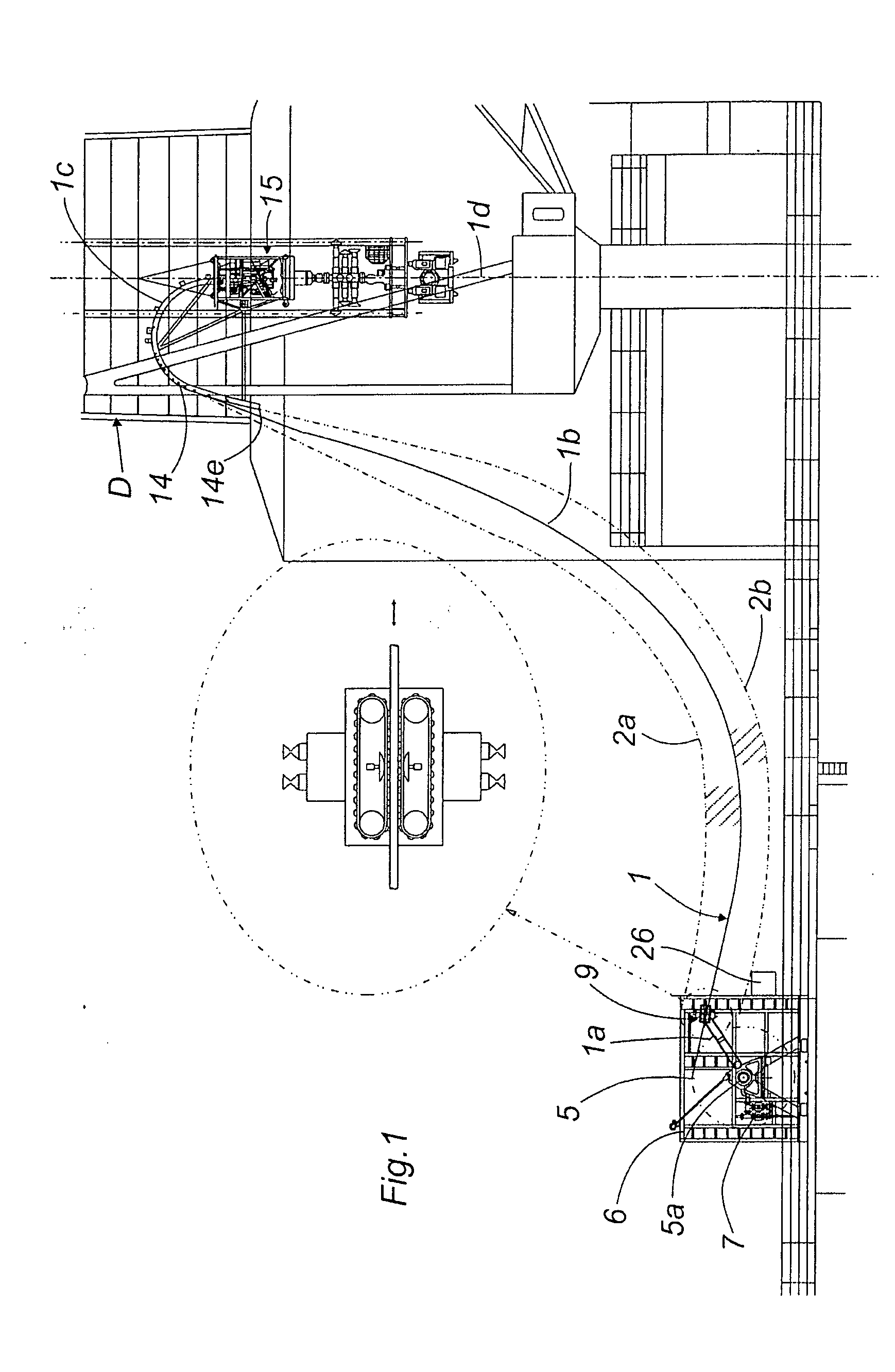
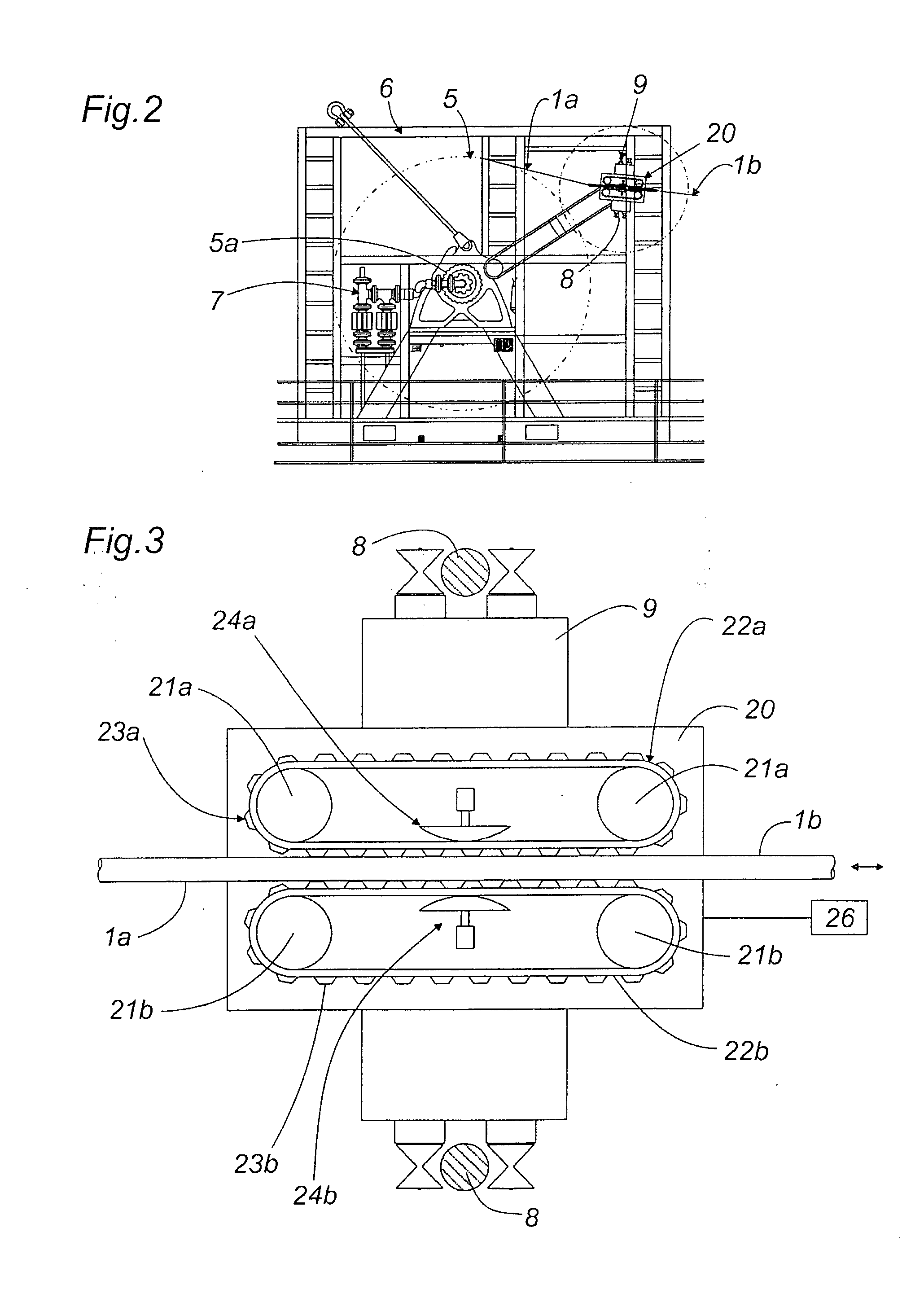
[0060]Referring now to the drawings, FIG. 1 shows a tubing handling system for injecting coiled tubing into an oil or gas well. The system has a reel 5 of tubing 1, rotatably mounted on its axis 5a on bearings in a frame 6. The reel is cylindrical and is driven in rotation around the bearings by a motor 7. The tubing 1 is spooled on and off the reel by a levelwind head 9. The levelwind head 9 has a pair of sheaves on each end that engage respective rails 8 extending parallel to the axis of rotation of the reel 5. The levelwind head 9 can move along the rails 8 parallel to the axis of the reel, to guide the tubing and distribute it onto and from the reel in an even manner. The lateral motion of the levelwind head along the rails 8 can be powered or free.

[0061]The reel 5 is mounted on the deck of a drilling platform, over an oil or gas well. The platform has a derrick injector head 15 of known design which is suspended from the derrick D. The derrick injector head 15 controls the rate...


PUM


Abstract

The invention relates to tubing handling apparatus for injecting tubing into and recovering the tubing from a wellbore. In an embodiment, the apparatus includes a storage reel of coiled tubing, a first injector head and a second injector head for injecting the tubing from the reel into the wellbore. The second injector head may be located between the storage reel and the wellbore, and the first injector head may be disposed between the storage reel and the second injector head. The first and second injector heads can control bending of a length of the coiled tubing from the reel which is passed between the first and second injector heads.

Description

FIELD OF THE INVENTION[0001]The present invention relates to tubing handling apparatus and associated methods. In addition, the invention relates to a gooseneck device for a tubing injector head.BACKGROUND TO THE INVENTION[0002]Tubing is commonly used in oil, gas and water wells, to convey fluids between the well and the surface. Coiled tubing is normally supplied in continuous lengths wound onto a reel, and is unwound from the reel as it is injected into the wellbore. Normally the injection of the coiled tubing into the wellbore is controlled by an injector head. In offshore wells, the tubing is injected into the well through a riser, which is secured to the wellhead on the seabed, and which forms a rigid and stationary conduit between the platform or drill ship at the surface, and the wellhead on the seabed. When the platform is subject to heave, the platform and derrick therefore move relative to the injector head attached to the stationary riser. In order to accommodate this rel...

Claims


Application Information

Patent Timeline
IPC IPC(8): E21B19/22E21B19/08B65H57/00
CPCE21B19/22E21B19/09
Inventor DREELAN, MICHAEL
Owner QSERV
Why Eureka
Try Eureka