

Acoustic baffle assembly
a technology of acoustic baffle and assembly, which is applied in the direction of instruments, machines/engines, transportation and packaging, etc., can solve the problems of not being able to use substrates, need to accommodate different configurations of hollow compartments, and undesirable sound transmission
- Summary
- Abstract
- Description
- Claims
- Application Information
AI Technical Summary
Benefits of technology
Problems solved by technology
Method used
Image

Examples
first embodiment
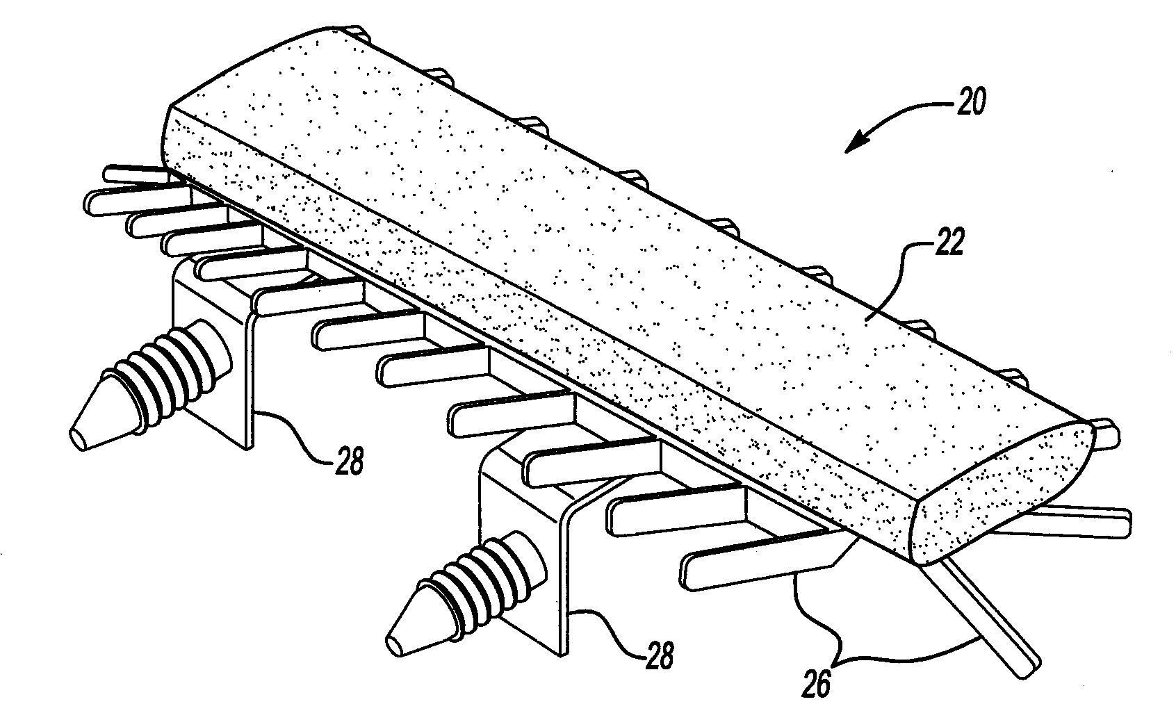
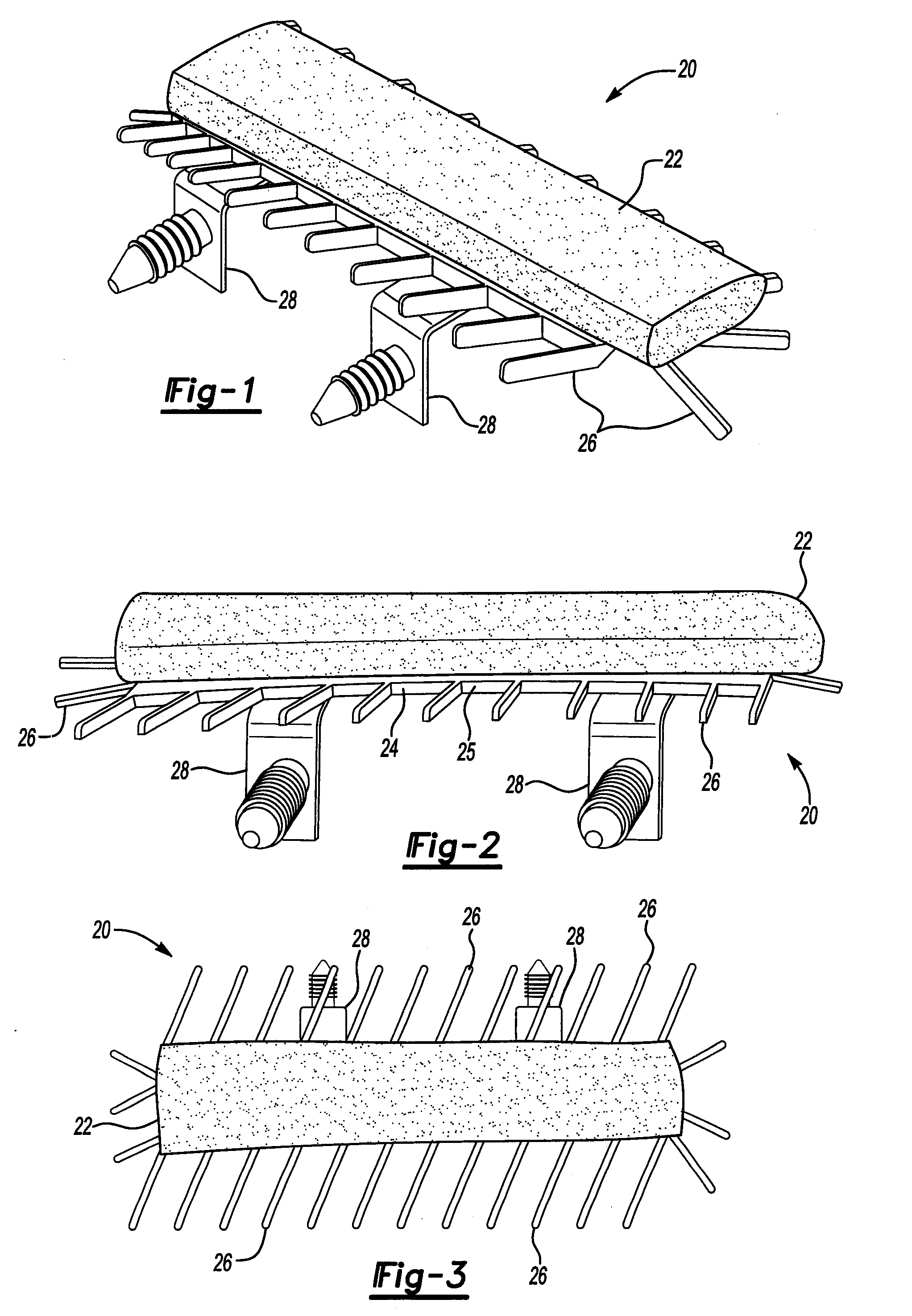
[0052]With reference to FIGS. 1-3, these figures illustrate three differing views of the present invention. As depicted, a baffle assembly 20 includes an expandable mass 22, typically a mastic, capable of expanding approximately 2000% volumetrically when activated. Any suitable mastic or expandable material can be used. In at least one embodiment, the expandable material can, upon exposure to sufficient heat, expand approximately 2000% volumetrically; in other embodiments, the expandable material may expand by approximately 500% to 3000% volumetrically. In the illustrated embodiment, the mastic is comprised of an ethylene vinyl acetate copolymer. Derivatives thereof and / or other thermoplastics (including thermoplastic elastomers) may also be used. Typically, the mastic may also contain one or more heat activatable blowing agents, in particular one or more latent chemical blowing agents, in amounts effective to provide the desired degree of expansion when the mastic is heated. Additi...
second embodiment
[0072]With reference to FIG. 14, an acoustic baffle assembly 120 made in accordance with the teachings of the present invention is illustrated. Acoustic baffle assembly 120 includes a substrate 122 having a central portion 124 and a plurality of elongate arms 126. In the illustrated embodiment, elongate arms 126 include outer tips 128 such that the outer tips 128 cooperate together to form a generally circular perimeter. In other embodiments, the individual arms may have varying lengths such that only some of the tips may cooperate to form the generally circular perimeter. In still other embodiments, other geometric configurations may be employed. For instance, the cross sectional configuration of the compartment may be more suited to oval or oblong substrate configurations. In the illustrated embodiment, each elongate arm 126 has substantially the same length and configuration. In other embodiments, elongate arms 126 of varying lengths may be employed. Also, in the illustrated embo...
PUM
| Property | Measurement | Unit |
|---|---|---|
| Fraction | aaaaa | aaaaa |
| Temperature | aaaaa | aaaaa |
| Mass | aaaaa | aaaaa |
Abstract
Description
Claims
Application Information