Electric machine

a technology of electric machines and motors, applied in the field of electric machines, can solve the problems of affecting the cooling effect of the stator, entail considerably more work and expense in production, and complex assembly process technology,

Active Publication Date: 2009-09-10
MINEBEAMITSUMI INC
View PDF5 Cites 22 Cited by
  • Summary
  • Abstract
  • Description
  • Claims
  • Application Information

AI Technical Summary

Benefits of technology

[0024]The construction according to the invention makes it possible not only to center and connect the flange to the stator in a space-saving way without using complex process technology, but also to realize a motor design in which the outside surface of the stator remains free since a separate housing for fixing the flanges is not necessary. This allows the heat generated during operation to be dissipated directly from the outside surface of the stator to the environment.

Problems solved by technology

In small electric motors, the available installation space is often limited so that the known methods of attaching the mounting flange on the motor housing either increase the size of the motor and, where installation space is limited, may no longer be an option, or the necessary process technology for assembly is complex and entails considerably more work and expense in production.
What is more, conventional motor housings are not optimized for cooling the stator when in operation.
This construction requires quite a lot of space and the special design of the housing including cooling channels is complex.
This goes to produce an electric machine having an extremely compact construction, which, however, in terms of cooling the stator is less favorable than the machine described initially.

Method used


Image

  • Electric machine
  • Electric machine
  • Electric machine

Examples


Embodiment Construction

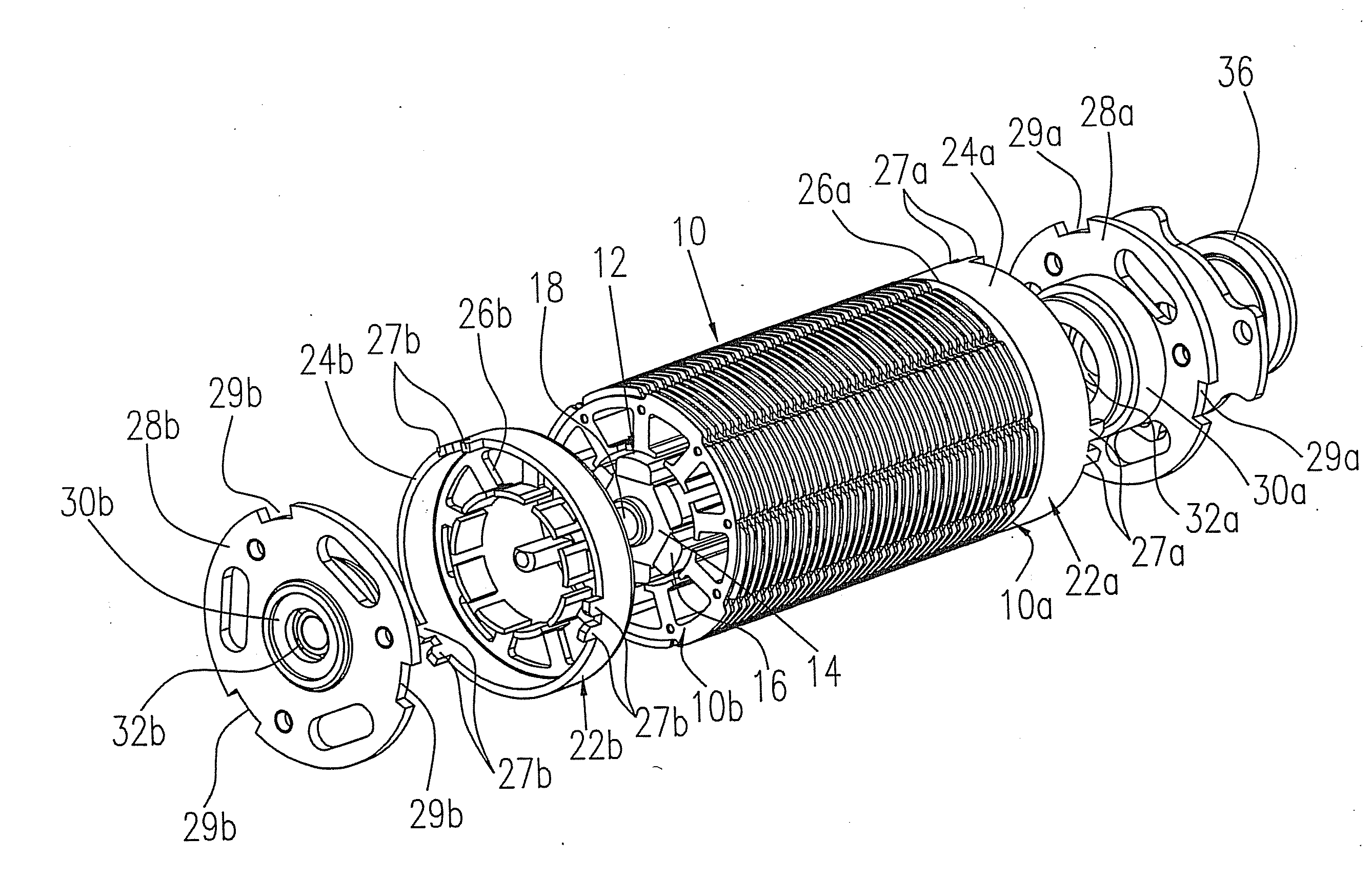
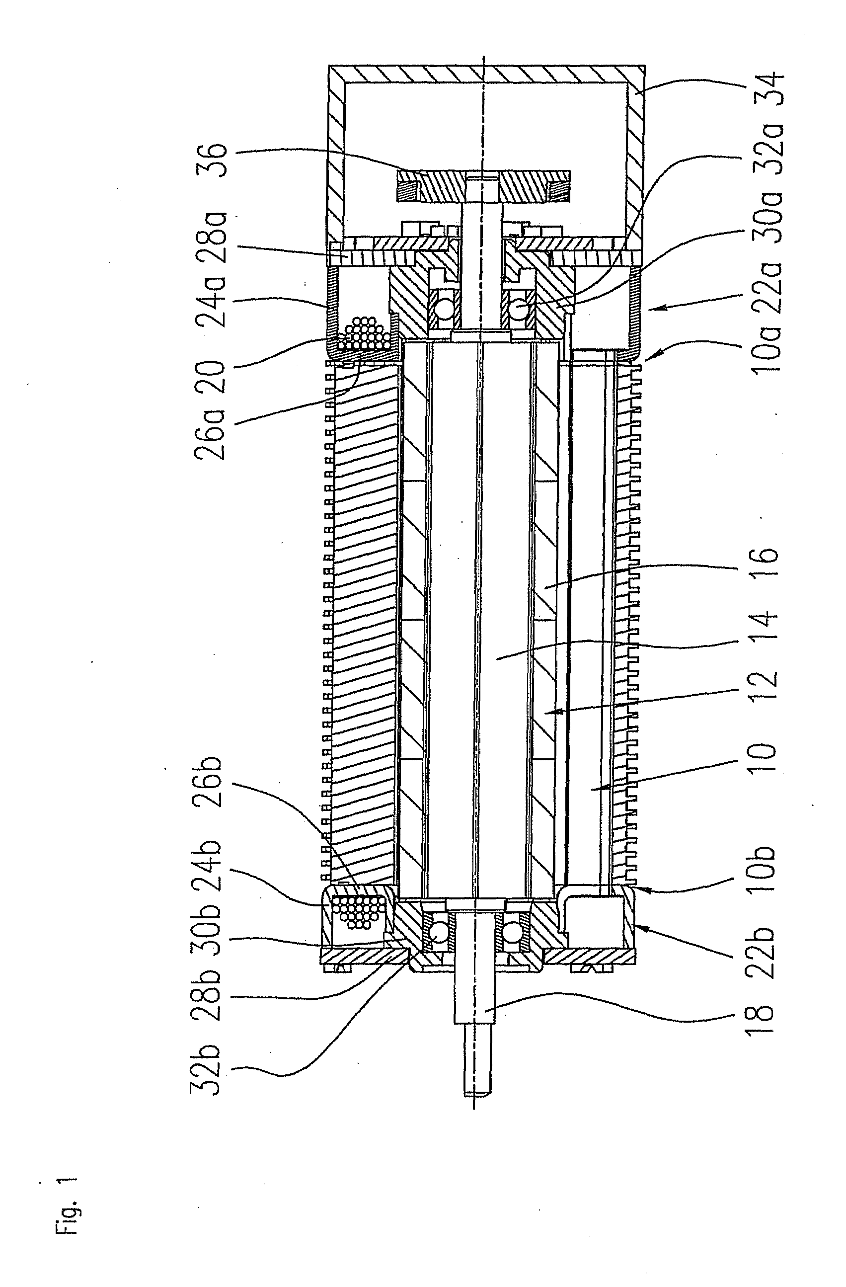
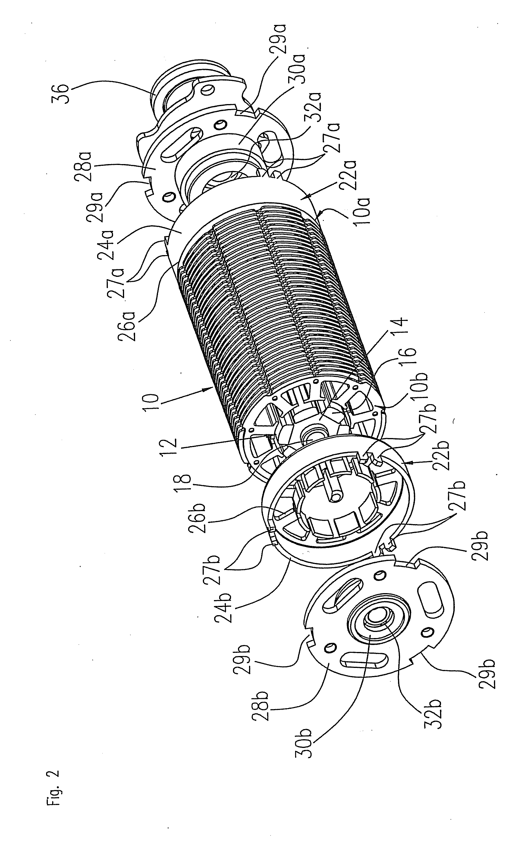
[0038]FIG. 1 shows a sectional view through a brushless dc motor that is constructed according to a first embodiment of the invention. The motor comprises a stator 10 and a rotor 12 that is enclosed by the stator 10. The rotor 12 comprises a magnet carrier 14 as well as permanent magnets 16 that are mounted on a shaft 18. The magnet carrier 14 may be made of a ferromagnetic material in order to form a back yoke for the permanent magnets 16.

[0039]The stator 10 comprises a back yoke ring and stator slots 46 and stator poles 44 that are formed on the inside circumference of the back yoke ring and which receive a stator winding 20. The stator 10 is made up of a plurality of stator laminations that are joined to form a lamination stack, as described in more detail below.

[0040]At each end face of the stator 10a and 10b, a flange arrangement 22a, 22b is connected to the stator 10. Each flange arrangement 22a, 22b comprises a first flange component 24a, 24b that is cup-shaped in form. The g...


PUM


Abstract

An electric machine having a rotor and a stator that encloses the rotor, and having a first flange arrangement on at least one end face of the stator, wherein the first flange arrangement has a first flange component that has a connecting surface which adjoins the first end face of the stator and whose geometry is adapted to the geometry of the end face of the stator so that a stator winding, which is wound onto the stator and the adjoining connecting surface, connects the stator and the first flange component to one another.

Description

FIELD OF THE INVENTION[0001]The invention relates to an electric machine that has a rotor and a stator and at least one flange arrangement that is disposed at an end face of the stator.BACKGROUND OF THE INVENTION[0002]A preferred field of application of the invention is in brushless dc motors and stepper motors as well as other permanent magnet motors that are configured as inner rotor motors. Inner rotor motors comprise a rotor arrangement that is mounted on a shaft and inserted coaxially into a stator arrangement. The stator body is generally made up of stamped metal laminations that carry windings. It comprises a back yoke ring on whose inner surface lie stator slots and stator poles that receive the stator winding.[0003]In the prior art, electric machines are generally built with metal housings and mounting flanges that are disposed on one or both end faces of the housing. First, the stator is constructed as an assembly in that the stator body is built up to form, for example, a...

Claims


Application Information

Patent Timeline
Patent Type & Authority Applications(United States)
IPC IPC(8): H02K5/16H02K3/34
CPCH02K1/146H02K1/16H02K5/18H02K5/1732H02K3/345
Inventor BOTTGER, AXELKREIENSEN, ULLRICH
Owner MINEBEAMITSUMI INC
Why Eureka
Try Eureka