
Light-extraction layer of light-emitting device and organic electroluminescence element employing the same

Inactive Publication Date: 2009-09-10
KK TOSHIBA
View PDF16 Cites 28 Cited by
  • Summary
  • Abstract
  • Description
  • Claims
  • Application Information

AI Technical Summary

Benefits of technology

[0013]According to embodiments of the present invention, highly efficient light extraction layer for light-emitting devices and organic electroluminescence elements excellent in light-extraction efficiency are provided.

Problems solved by technology

The problem of the confined light is liable to occur not only in an organic EL element but also in other devices, such as liquid crystal displays and lighting devices, which comprise light-emitting parts having higher refractive indexes than air.
However, the two-dimensional diffraction structure has too small diffraction efficiency to sufficiently improve the light-extraction efficiency.
Accordingly, an expensive apparatus and complicated procedures are necessary and hence it costs a lot to produce the diffraction structure.
In addition, since the periodical structure causes uneven brightness on the light-emitting surface, it is necessary to take some measures when applied to displays or other devices required to have uniformity of brightness on the light-emitting surface.
If the size distribution is narrow or if the volume fraction is small, the light-scattering layer cannot scatter the light sufficiently.
On the other hand, if the size distribution is broad, it is difficult to ideally arrange the particles in the resin.
Further, if the particles having a broad size distribution are incorporated in a large volume fraction, the obtained light-scattering layer is remarkably poor in flatness and accordingly the light-emitting part in the form of a thin layer is also poor in flatness to lower reliability of the EL element considerably.
Thus, this is a dilemma.
20% and hence the effect of scattering is so small that it cannot be expected to improve the light-extraction efficiency remarkably.

Method used


Image

  • Light-extraction layer of light-emitting device and organic electroluminescence element employing the same
  • Light-extraction layer of light-emitting device and organic electroluminescence element employing the same
  • Light-extraction layer of light-emitting device and organic electroluminescence element employing the same

Examples


example 1

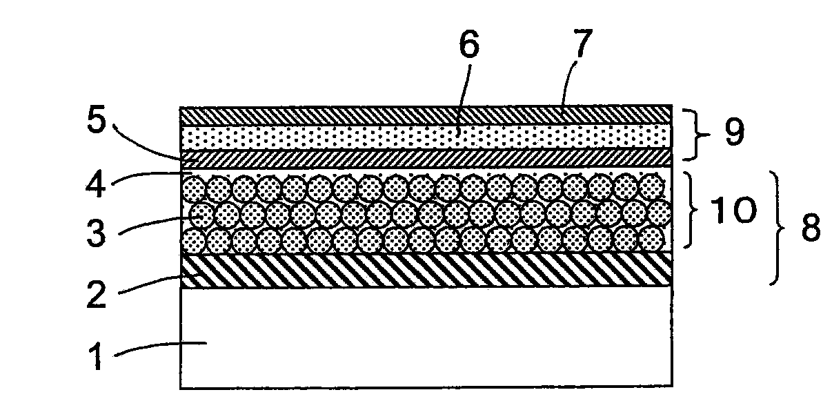
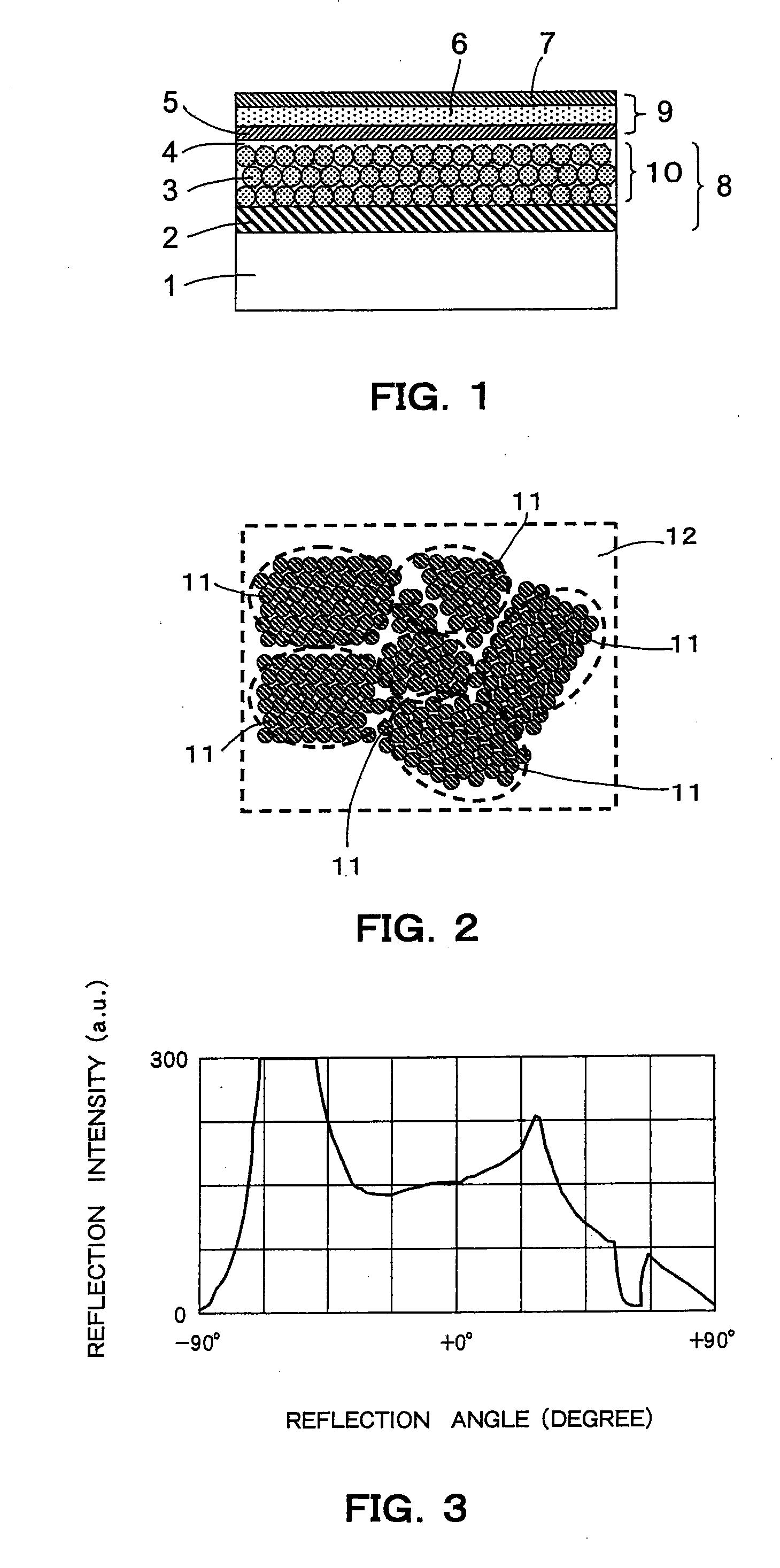
[0056]A glass substrate (refractive index: 1.48; TEMPAX Float [trademark], manufactured by Schott Nippon K.K.) as the substrate was prepared. After ITO was sputtered on the glass substrate to form a buffer layer of 10 nm thickness, silver was sputtered thereon to produce a reflecting layer of 200 nm thickness, and then ITO was sputtered again thereon to form a protective layer of 10 nm thickness. Independently, silica particles (mean particle size: 380 nm; CV value: 5%; n=1.42; PL-13 [trademark], manufactured by Fuso Chemical Co., Ltd.), which were beforehand surface-modified with a silane-coupling agent to have surfaces modified with acryl groups, were dispersed in three-functional acrylic monomer (ETPTA: ethoxylated trimethylolpropane triacrylate; n=1.47; manufactured by Aldrich Corp.) in the volume fraction of 60%. The prepared dispersion was spin-coated on the substrate at 2000 rpm, and then subjected to bake treatment on a hot-plate at 150° C. for 1 hour so as to thermally cure...

example 2

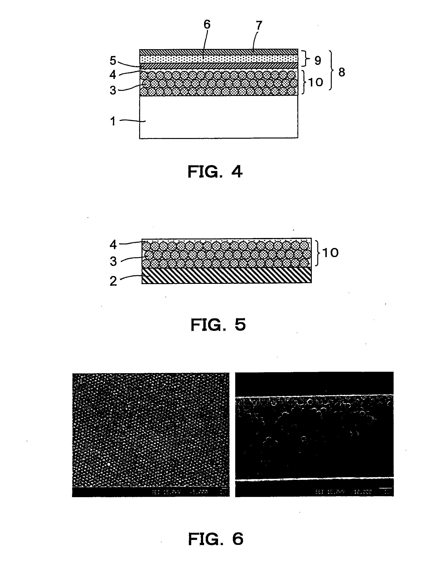
[0057]The procedures of Example 1 were repeated to form a three-dimensional diffraction layer on the substrate. Thereafter, the sample was immersed in 5% hydrofluoric acid aqueous solution for 5 minutes, and washed with flowing water for 15 minutes to remove only the silica particles accumulated in the layers. A section of the obtained sample was observed by SEM to confirm that only the particles were clearly removed and thereby that a three-dimensional diffraction layer comprises air bubbles as the fine particles and acrylic polymer as the matrix was produced (FIG. 7). In the same manner as in Example 1, a light-emitting layer was then formed on the three-dimensional diffraction layer. The sample was sealed with another glass substrate in nitrogen atomosphere, to obtain a top emitting type organic EL element.

example 3

[0058]The procedures of Example 1 were repeated except that the three-functional acrylic monomer was changed into trimethylol propane triacrylate (n=1.47; manufactured by Aldrich Corp.), to prepare a silica-dispersion, which was then spin-coated on the substrate at 2000 rpm. The sample was then subjected to bake treatment on a hot-plate at 150° C. for 1 hour, to evaporate the acrylic monomer. Thus, a three-dimensional diffraction layer comprised the silica particles and air as the matrix was produced. A section of the obtained sample was observed by FE-SEM to confirm that the particles were arranged like a crystal structure to form 15 layers (FIG. 8). This three-dimensional diffraction layer and the reflecting layer constituted a light-extraction layer according to the present invention. In the same manner as in Example 1, a light-emitting layer was then formed on the three-dimensional diffraction layer. The sample was sealed with another glass substrate in nitrogen atomosphere, to ...


PUM


Abstract

The present invention provides a highly efficient light-extraction layer and an organic electroluminescence element excellent in light-extraction efficiency. The light-extraction layer of the present invention comprises a reflecting layer and a three-dimensional diffraction layer formed thereon. The diffraction layer comprises fine particles having a variation coefficient of the particle diameter of 10% or less and of a matrix having a refractive index different from that of the fine particles. The particles have a volume fraction of 50% or more based on the volume of the diffraction layer. The particles are arranged to form first areas having short-distance periodicity, and the first areas are disposed and adjacent to each other in random directions to form second areas. The organic electroluminescence element of the present invention comprises the above light-extraction layer.

Description

CROSS-REFERENCE TO RELATED APPLICATIONS[0001]This application is based upon and claims the benefit of priority from the prior Japanese Patent Applications No. 2008-59224, filed on Mar. 10, 2008; the entire contents of which are incorporated herein by reference.BACKGROUND OF THE INVENTION[0002]1. Field of the Invention[0003]The present invention relates to a highly efficient reflecting plate used for a light-emitting device, and also relates to an organic electroluminescence element excellent in light-extraction efficiency employing the same.[0004]2. Background Art[0005]In an organic electroluminescence element (hereinafter, often referred to as “organic EL element”), the refractive index of the light-emitting part is generally approx. 2.0, which is higher than that of air 1.0. Accordingly, because of total reflection at the interface between the element and air, approx. 80% of the emitted light is confined and travels in the element, and hence cannot be extracted out (see, C. F. Mad...

Claims


Application Information

Patent Timeline
IPC IPC(8): H01J1/63G02B6/10
CPCH01L51/5262H01L2251/5315H01L51/5271H10K50/856H10K2102/3026H10K50/858H10K50/85
Inventor NAKANISHI, TSUTOMUFUJIMOTO, AKIRAMATAKE, SHIGERUASAKAWA, KOJI
Owner KK TOSHIBA
Learn More