
Inorganic oxide and phosphor

Inactive Publication Date: 2006-04-18
PANASONIC CORP
View PDF9 Cites 91 Cited by
  • Summary
  • Abstract
  • Description
  • Claims
  • Application Information

AI Technical Summary

Benefits of technology

[0019]Therefore, with the foregoing in mind, it is a first object of the present invention to provide a novel oxide that can be a phosphor host of a highly efficient phosphor or a highly efficient phosphor itself, and a novel phosphor including the oxide as the phosphor host or made of the oxide. It is a second object of the present invention to provide a novel phosphor that is excited with blue light and emits light including a yellowish component, which is suitable especially as a light-emitting device to which a blue LED is applied. Furthermore, it is a

Problems solved by technology

On the other hand, almost no development of the phosphors different from the YAG:Ce host phosphor has been performed, partly because it requires significant effort.
On the other hand, a blue exciting yellow phosphor other than the YAG:Ce host phosphor for a light-emitting device (e.g., white LED) in which the blue LED and a blue exciting yellow phosphor other than the YAG:Ce host phosphor are combined has a fatal problem in that the luminescent efficiency under the excitation of blue light is at least 10% lower than that of the YAG:Ce host phosphor, and has a secondary problem in that there is only a little of a red light-emitting component, which is required especially when it is used for illumination.
At the same time, a light-emitting device in which the blue LED and a blue exciting yellow phosphor other than the YAG:Ce host phosphor are combined has a problem in that the light-emitting intensity is low, the intensity of a red light-emitting component is low, and this light-emitting is inferior to a device in which the YAG:Ce host phosphor is used.

Method used


Image

  • Inorganic oxide and phosphor
  • Inorganic oxide and phosphor
  • Inorganic oxide and phosphor

Examples


embodiment 1

[0108]Hereinafter, the inorganic oxides and the phosphors of the present invention will be described as Embodiment 1 of the present invention.

[0109]One embodiment of the inorganic oxides that can be a phosphor or a phosphor host of the present invention is expressed by a chemical formula I below and preferably has the crystal structure of garnet.

MLn2QR4O12  (I)

[0110]where in the chemical formula I, M is at least one element selected from the group consisting of Mg, Ca, Sr, and Ba; Ln is at least one rare earth element selected from the group consisting of Sc, Y, La, Ce, Pr, Nd, Sm, Eu, Gd, Tb, Dy, Ho, Er, Tm, Yb, and Lu, and preferably Sc, Y, La, and Gd; Q is at least one element selected from the group consisting of Si, Ge, Sn, and Pb, and preferably Si and Ge; and R is at least one element selected from the group consisting of B, Al, Ga, In, and Tl, preferably Al and Ga.

[0111]In the crystal structure, a part of M can be substituted with at least one element (e.g., Zn) selected fro...

embodiment 2

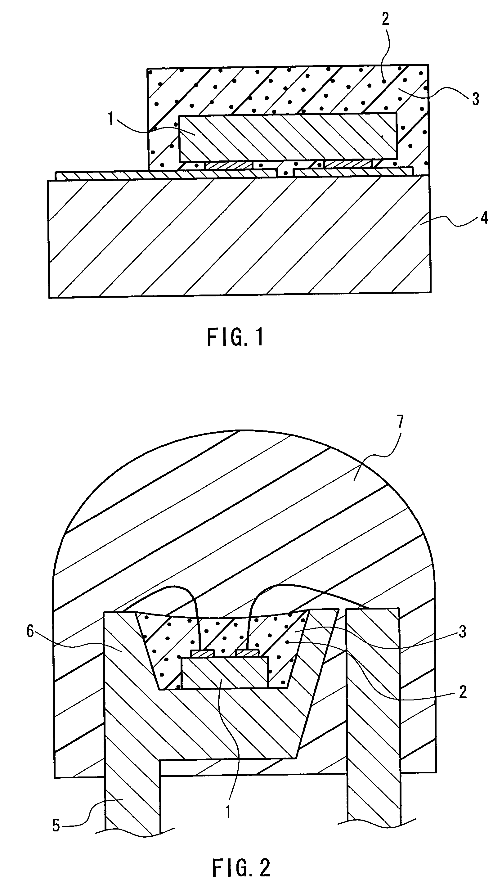
[0161]FIGS. 1 to 3 are longitudinal sectional views of semiconductor light-emitting elements as examples of the light-emitting element of the present invention. FIG. 1 shows a typical example of a semiconductor light-emitting element having a structure in which a light-emitting element 1 is conductively mounted on a sub-mount element 4, and the light-emitting element 1 is sealed with a resin package that contains at least the phosphor 2 of the present invention as described above (hereinafter, referred to as the phosphor 2 of the present invention) and also serves as a phosphor layer 3.

[0162]FIG. 2 shows a semiconductor light-emitting element having a structure in which a light-emitting element 1 is conductively mounted on a cup 6 provided in a mount lead of a lead frame 5, a phosphor layer 3 formed of a resin containing at least the phosphor 2 of the present invention is provided in the cup 6, and the whole is sealed with a sealing resin 7.

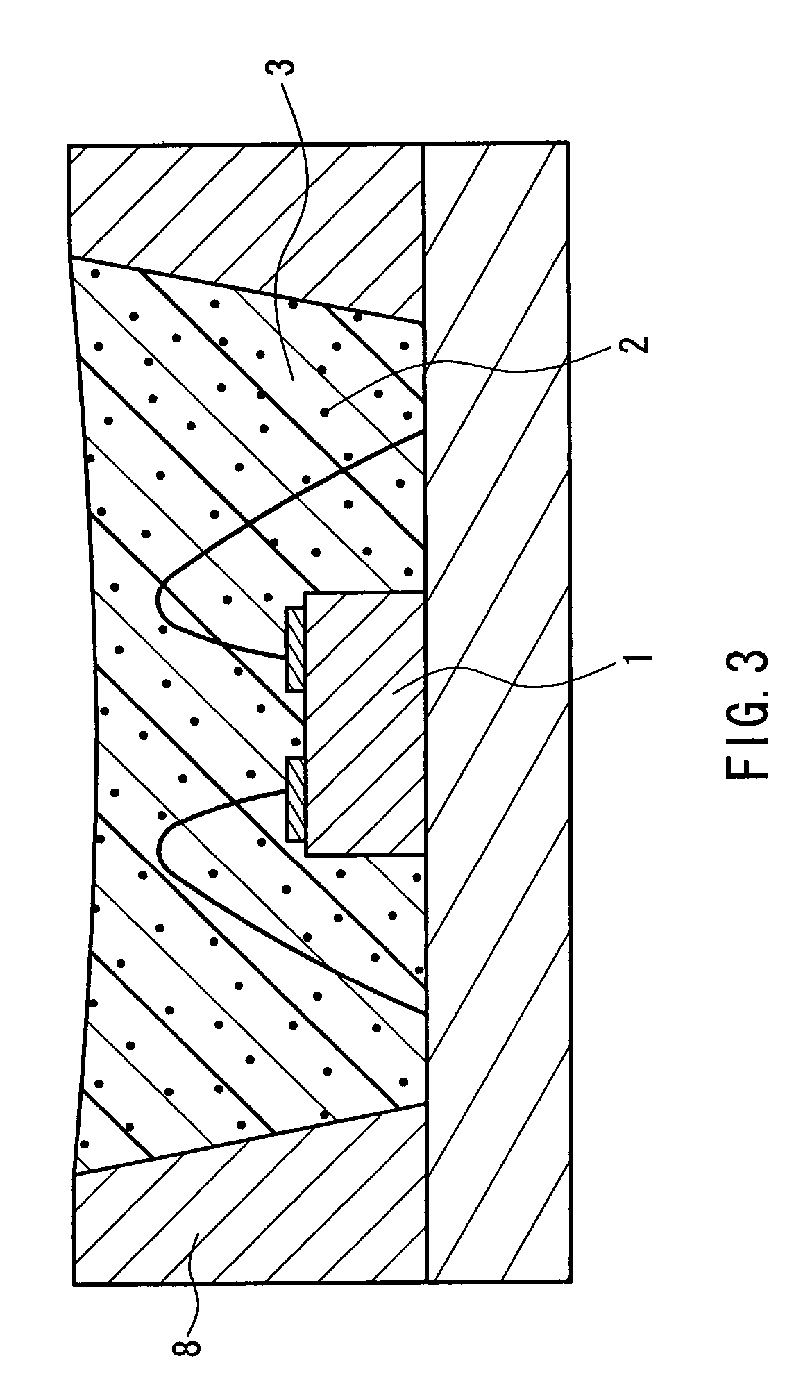
[0163]FIG. 3 shows a semiconductor light-e...

example 1

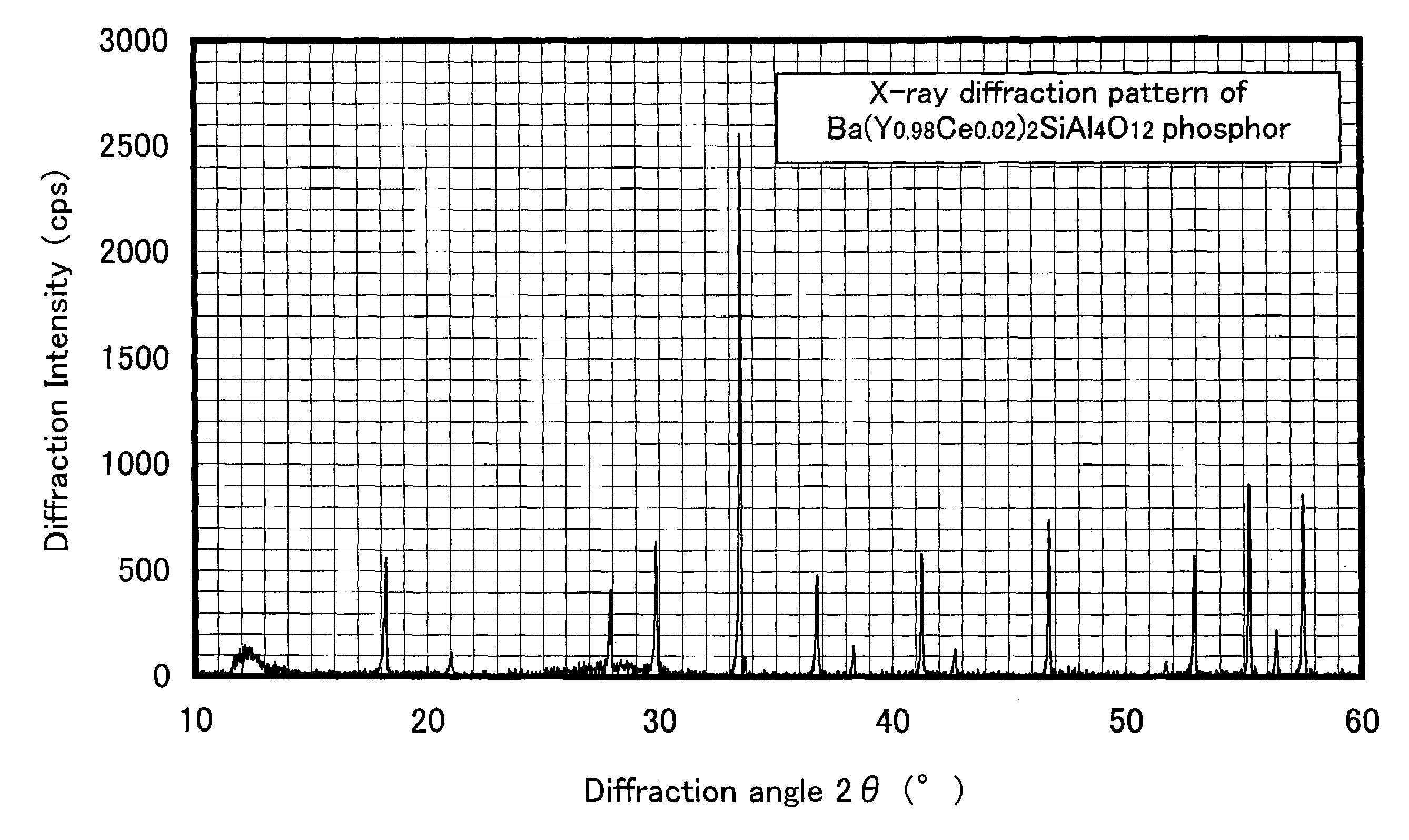
[0173]Hereinafter, a method of producing a Ba(Y0.98Ce0.02)2SiAl4O12 inorganic oxide, that is, a BaY2SiAl4O12:Ce3+ phosphor, and the characteristics thereof will be described in Example 1 of the present invention.

[0174]The following inorganic compound powders were used as the phosphor raw materials (inorganic oxide raw materials).[0175](1) barium carbonate (BaCO3): 9.87 g, the purity 99.95%[0176](2) yttrium oxide (Y2O3): 11.07 g, the purity 99.99%[0177](3) aluminum oxide (Al2O3): 10.20 g, the purity 99.99%[0178](4) silicon dioxide (SiO2): 3.07 g, the purity 99.9%[0179](5) cerium oxide (CeO2): 0.34 g, the purity 99.99%

[0180]In Example 1, no flux was used for simplicity.

[0181]The phosphor raw materials were mixed sufficiently with an automatic mill, and then the mixed raw materials were fed into a firing container and were fired under the following firing conditions.

[0182]firing atmosphere: in the air

[0183]firing temperature: 1500° C.

[0184]firing time: two hours

[0185]For simplification...


PUM

PropertyMeasurementUnit
Percent by atomaaaaaaaaaa
Temperatureaaaaaaaaaa

Abstract

The present invention provides an inorganic oxide made of MLn2QR4O12, where M is at least one element selected from the group consisting of Mg, Ca, Sr, and Ba; Ln is at least one rare earth element selected from the group consisting of Sc, Y, La, Ce, Pr, Nd, Sm, Eu, Gd, Tb, Dy, Ho, Er, Tm, Yb, and Lu; Q is at least one element selected from the group consisting of Si, Ge, Sn, and Pb,; and R is at least one element selected from the group consisting of B, Al, Ga, In, and Tl. This inorganic oxide serves as a phosphor or a phosphor host and if it contains ions capable of being the luminescent center, it becomes a phosphor emitting fluorescent light. Thus, a novel oxide that can be a phosphor host of a high efficiency phosphor or the phosphor itself and a novel phosphor are provided.

Description

FIELD OF THE INVENTION[0001]The present invention relates to novel inorganic oxides and phosphors.BACKGROUND OF THE INVENTION[0002]Conventionally, a large number of phosphor materials in which ions capable of emitting fluorescent light are doped into inorganic compound materials (hereinafter, referred simply as “phosphors”) have been known. Phosphors have the properties of emitting ultraviolet, visible and infrared light by action of external exciting means such as irradiation of electromagnetic waves (e.g., electron beams, X-rays, ultraviolet rays, visible light, etc.) or application of an electric field, and therefore are used in a large number of photoelectric transducers or photoelectric conversion devices. Examples thereof are light-emitting devices such as white light-emitting diodes (hereinafter, referred to as “white LED”), fluorescent lamps, electron beam tubes, plasma display panels, inorganic electroluminescent displays, and scintillators.[0003]The phosphors will be descr...

Claims


Application Information

Patent Timeline
IPC IPC(8): C09K11/79C09K11/80C04B35/50C01B13/18C01B33/24C01B33/26C01B35/18C01F17/00C01G15/00C01G17/00C04B35/26C04B35/44C09K11/77C30B29/22C30B29/28G09F13/20H01J11/22H01J11/34H01J11/42H01L33/48H01L33/50H01L33/56
CPCC04B35/01C04B35/18C04B35/2641C04B35/44C04B35/6268C04B35/6303C09K11/7774H01L2224/48257C04B2235/3206C04B2235/3208C04B2235/3213C04B2235/3215C04B2235/3224C04B2235/3225C04B2235/3229C04B2235/3286C04B2235/3287C04B2235/3293C04B2235/3409C04B2235/3418C04B2235/445C04B2235/764C04B2235/768H01L2224/48091H01L2224/48247H01L2924/00014C09K11/77742C09K11/77744
Inventor OSHIO, SHOZO
Owner PANASONIC CORP
Learn More