Methods and systems for detection and location of multiple emitters

a technology of multiple emitters and detection methods, applied in the field of signal emission, can solve the problems of short up-time characteristics of ptt signals, insufficient detection time for most conventional single collection systems, and no solution or only invalid solution

Inactive Publication Date: 2009-09-10
L 3 COMM INTEGRATED SYST
View PDF25 Cites 101 Cited by
  • Summary
  • Abstract
  • Description
  • Claims
  • Application Information

AI Technical Summary

Benefits of technology

[0006]Disclosed herein are systems and methods for detection and geolocation of multiple emitters (e.g., a network of multiple transmitters) that are emitting RF signals on a common frequency. Using the disclosed systems and methods, multiple collection systems may be tasked to “camp” on a selected frequency until a RF signal of interest is detected. The disclosed systems and methods may be implemented to separate, geolocate, and / or determine the number of emitters (e.g., radio users) emitting on a common RF frequency. Examples of radio communication environments in which a network of multiple emitters may be transmitting on a common frequency include, but are not limited to, a network of PTT radios, multiple base stations of a cellular telephone network, multiple weather broadcast stations, etc. Communicating multiple emitters of any other type of communication networks that use the same frequency may also be separated, geolocated, and / or counted. In one exemplary embodiment, the disclosed systems and methods may be advantageously implemented in one exemplary embodiment to accurately separate and precisely geolocate multiple speakers communicating on a common frequency.

Problems solved by technology

However, only one of these possible geo-locations is real, the other possible geo-locations in the set are purely mathematical solutions that are not the real location of the radio emitter.
When operating under this assumption, a network of multiple emitters transmitting on the same frequency actually act to interfere with each other and the conventional geolocation system will yield no solution or only an invalid solution.
One major obstacle to accomplishing this goal is the short up-time characteristics of these PTT signals.
Most conventional single collection systems will not have sufficient time to detect the signal activity, queue, collect, and process for emitter geolocation.
Even if the signal can be detected, there isn't enough good signal captured to allow computation of an accurate geolocation or the determination of the number of users on the selected frequency channel setting.
Another obstacle to accurate geolocation and number determination is the close proximity of the users in a PTT network given the line-of-sight limitations of these types of radios.

Method used


Image

  • Methods and systems for detection and location of multiple emitters
  • Methods and systems for detection and location of multiple emitters
  • Methods and systems for detection and location of multiple emitters

Examples


Embodiment Construction

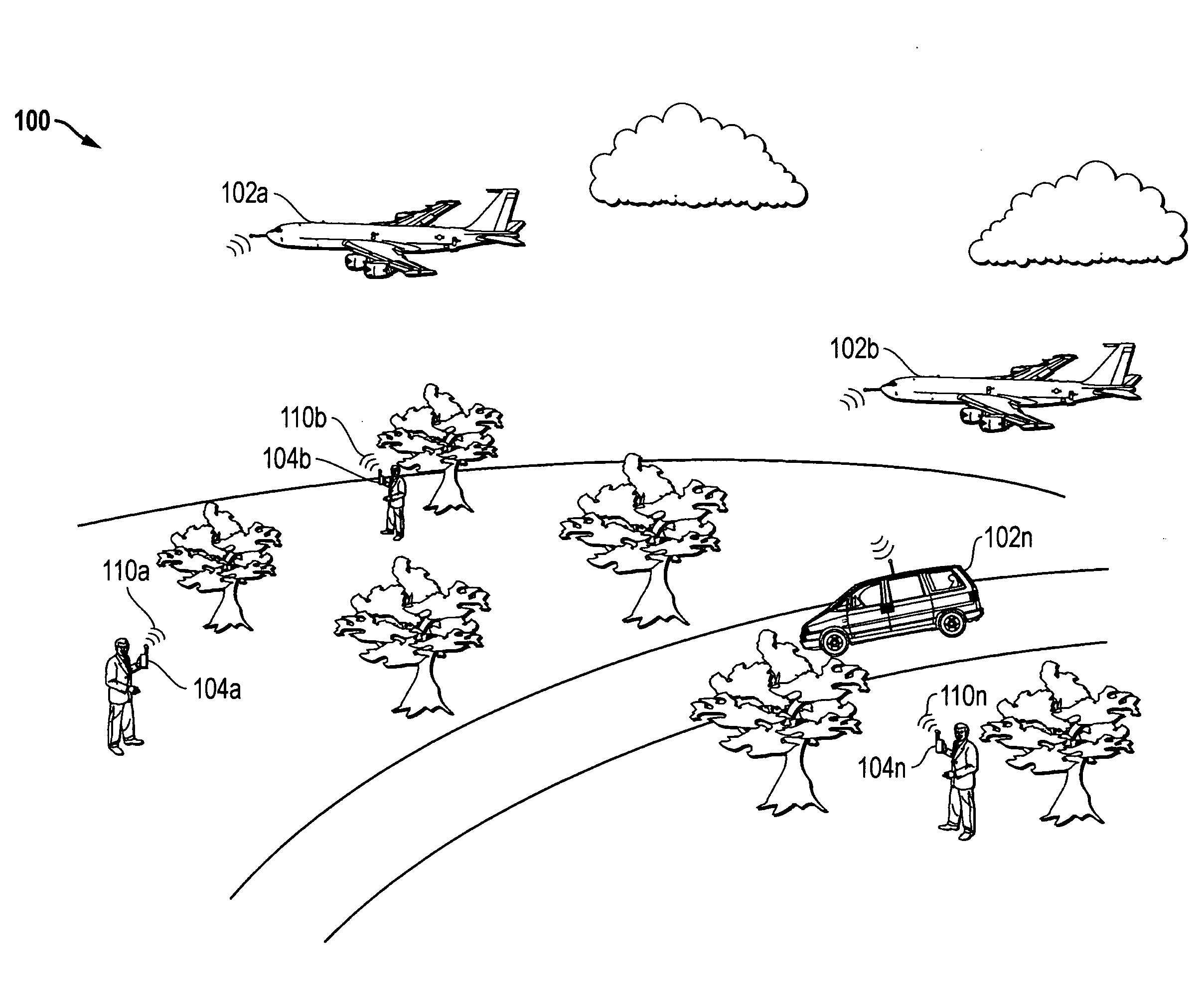
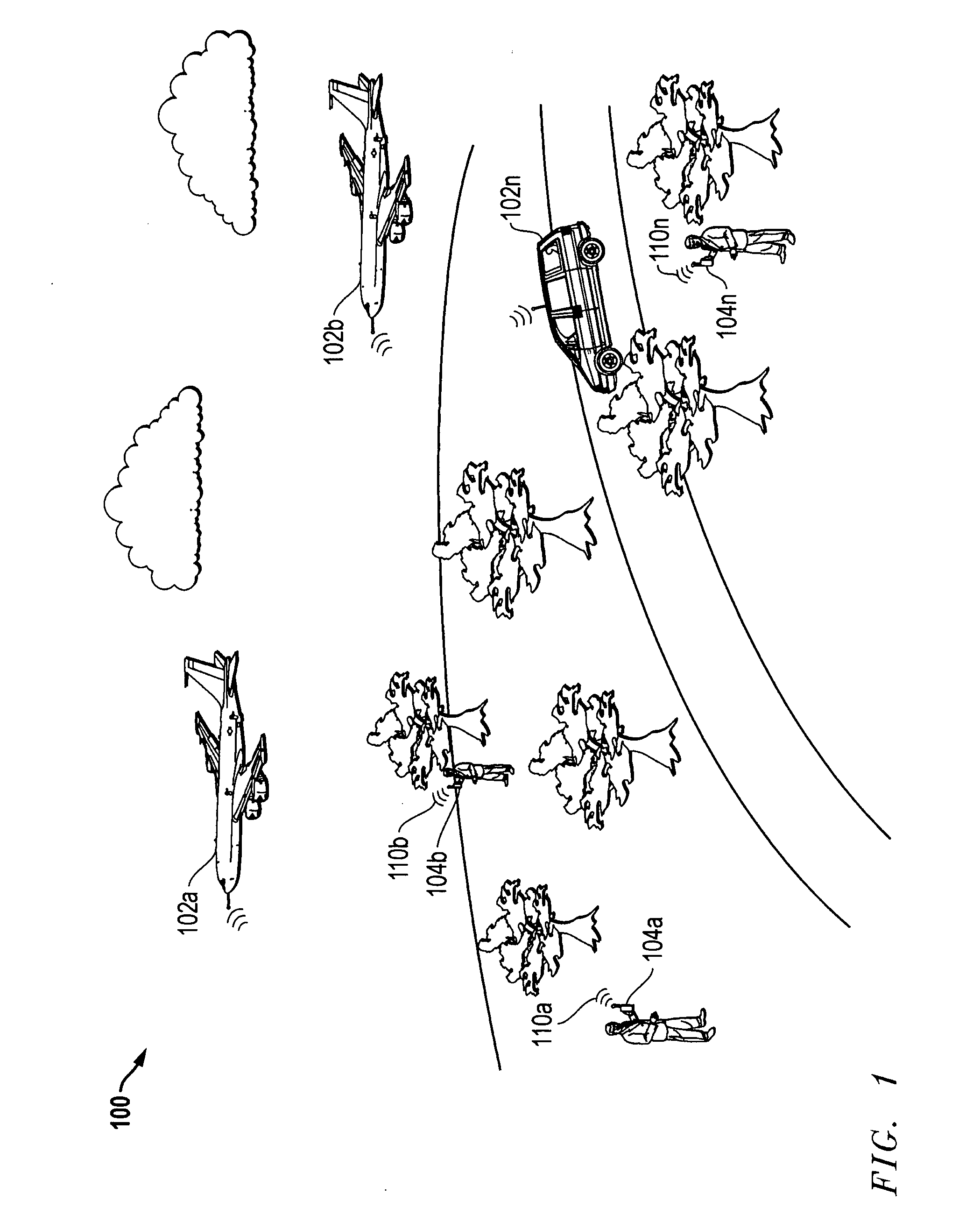
[0017]FIG. 1 illustrates one exemplary embodiment of an RF emissions environment 100 (in this case a radio communication environment) in which multiple emitters in the form of PTT radios 104a and 104b through 104n are communicating in a radio communication network via respective RF signals 110a and 110b through 110n transmitted on a common frequency. In the illustrated embodiment, each emitter 104 is a ground-based mobile emitter (in this case a “walkie talkie” type radio) carried by a human being that is stationary and emitting from a fixed location. However, it will be understood that the disclosed systems and methods may be practiced in radio communication environments in which any type, number and / or combination of different types of emitters are transmitting on a common frequency including, but are not limited to, multiple base stations of a cellular telephone network, cell phone devices, multiple weather broadcast stations, radar signal sources, microwave sources, etc. Further...


PUM


Abstract

Systems and methods for detection and geolocation of multiple emitters that are emitting RF signal energy on a common frequency, and that may be implemented to separate, geolocate, and / or determine the number of emitters (e.g., radio users) emitting on a common RF frequency. Real-time signal qualification processing may be employed to continuously monitor and collect incoming receiver tuner data for signal activity and ignore irrelevant noise data. Each set of data blocks from an emitter transmission signal may be defined as an emission cluster, and a set of time difference of arrival (TDOA) / frequency difference of arrival (FDOA) pairs may be computed for each emission cluster with each TDOA / FDOA pair yielding a geolocation result. A statistical qualification method may be used to produce a final geolocation answer from each set of emission cluster geolocation results, and a geolocation error ellipse computed for the final geolocation answer of each emission cluster. The final geolocation answer of each emission cluster may be run through a correlation and fusion algorithm.

Description

FIELD OF THE INVENTION[0001]The present invention relates generally to signal emissions, and more particularly to detection and location of signal emitters.BACKGROUND OF THE INVENTION[0002]TDOA / FDOA techniques have been employed in the past to determine the geolocation of emitters of electromagnetic radiation, such as radio frequency (“RF”) emissions. Using such techniques, the time difference (TDOA) in reception of a radio signal received at the sensing platforms of two spaced apart aircraft may be used to define a hyperboloid upon which the RF emitter of interest is located. Frequency difference (FDOA) in reception of the same radio signal at the sensing platforms of the two spaced apart aircraft may be generated by flying the spaced apart aircraft at different velocities and headings relative to the RF emitter, and may be used to further resolve the geo-location of the radio emitter. In this regard, assuming that the RF emitter of interest is located on the surface of the earth, ...

Claims


Application Information

Patent Timeline
Patent Type & Authority Applications(United States)
IPC IPC(8): G01S13/93G01S1/24
CPCG01S5/12G01S5/0009G01S5/0268G01S5/06G01S5/0244G01S5/0249G01S5/0246
Inventor CHUNG, HYO K.LE, PHUONG H.PARKER, JOHN M.REID, DAVID L.ROBERTSON, MARK A.
Owner L 3 COMM INTEGRATED SYST
Why Eureka
Try Eureka