Implantable access port

a technology of access ports and access ports, applied in the field of medical devices, can solve the problems of coagulation of blood or other materials in the system between uses, explantation of devices, and most patients that receive implantable access ports are either immune compromised, or are in danger of becoming immune compromised, so as to achieve effective reservoir cleaning and enhance the flow of material from the reservoir into the outlet and out of the access port.

Inactive Publication Date: 2009-09-10
ANGIODYNAMICS INC
View PDF54 Cites 137 Cited by
  • Summary
  • Abstract
  • Description
  • Claims
  • Application Information

AI Technical Summary

Benefits of technology

[0011]In each of the embodiments of the invention, at least a portion of the reservoir may thus be formed to have a parabolic, hemispherical, or semi-hemispherical shape in cross-section. With the reservoir outlet formed in a portion of the curvilinear side wall of the bowl-shaped reservoir, the smooth flow of material from the reservoir into the outlet and out of the access port is enhanced.
[0012]Additionally, the design of the reservoir outlet and the reservoir shape and size assure for a more effective reservoir cleansing when the port is flushed with a solution, for example an aqueous saline solution, between uses. The implantable access device of this invention can be thus used for the introduction of therapeutic agents, for the infusion or withdrawal of fluids, or for the introduction of sensing, sampling, or treatment devices to another implanted device, or to body regions within the patient.

Problems solved by technology

A major problem with implanted vascular access systems, and in particular access ports, is the occlusion of the system by coagulated blood or other material between uses.
As known, occlusion occurrences can lead to patient complications such as systemic infection, pocket infection, extravasation of medications, and port failure, all of which may lead to an explant of the device.
Further, most patients that receive implantable access ports are either immune compromised, or are in danger of becoming immune compromised.
These complications can therefore have a serious effect on the patient.
The growth of such occlusive substances, however, occurs through time and appears to occur at a much higher rate in access ports with edges and gaps present in the flow path.
Although access ports with cylindrical reservoirs have proven to be quite successful and gained wide acceptance and usage as described above, problems do exist with this type of construction.

Method used


Image

  • Implantable access port
  • Implantable access port
  • Implantable access port

Examples


first embodiment

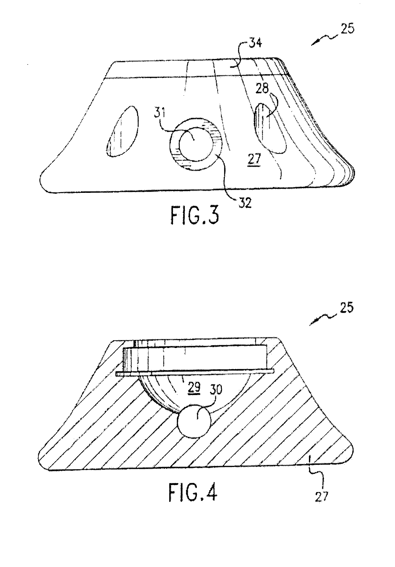
[0065]the implantable access port of this invention is illustrated in FIGS. 3 through 6. An implantable access port 25 is illustrated having a base 27 provided with a series of radially spaced suture holes 28, in known fashion. Here, however, in contrast to the known types of access ports, the access port 25 is formed to have a bowl-shaped reservoir 29, as best seen in FIGS. 4 and 6. The bowl-shaped reservoir is defined by a single smooth-surfaced wall which defines an open top of the reservoir, and a focus or center point at the “bottom” or center of the reservoir. The wall of the reservoir thus comprises a continuous curvilinear side wall.

[0066]The bowl-shaped reservoir, in all of the embodiments of the present invention, may thus be parabolic in shape, as well as hemispherical or semi-hemispherical when viewed in cross-section. The bowl-shaped formation of the reservoir 29 in the base 27 of the access port in such a manner thus allows for the reservoir to be made with the walls a...

second embodiment

[0071]the implantable access port of this invention is illustrated in FIGS. 7 through 9. The implantable access port 125 of FIGS. 7-9 includes a base 127 having a radially spaced series of suture holes 128 defined therein, as known. The suture holes may be filled with a penetrable material, for example an elastomeric material, for otherwise filling the openings within the base in order to limit tissue in-growth into the suture holes or openings.

[0072]Still referring to FIGS. 7-9, the access port 125 has a bowl-shaped reservoir 129 defined within and as a part of the base of the access port. As with the reservoir 29 of FIGS. 3-6, the bowl-shaped reservoir 129 is once again defined by a continuous smooth-surfaced wall, for example a curvilinear wall, which defines an open top of the reservoir and an opposed bottom having a focus or center point thereat, the bottom or bottom portion of the reservoir once again being that portion of the reservoir opposed to and spaced farthest from the ...

third embodiment

[0076]the invention is illustrated in FIGS. 10-14. In this exemplary embodiment, the implantable access port 225 for use in transferring a fluid transdermally between an external fluid storage or dispensing device and a site within a patient's body can comprise a base 227 (such as shown, for example, in FIGS. 15-19), a means for increasing the purging performance of the port, and a septum secured to the base and enclosing a reservoir within the base. In one aspect, the means for increasing the purging performance of the port can comprise a bowl-shaped reservoir 229 defined within the base by a smooth surfaced wall, a reservoir outlet 230, and an outlet passageway 231 positioned in operative communication with the reservoir outlet. In one exemplary aspect, the reservoir 229 has a top edge, a bottom portion and a side portion that extends between the bottom portion and the top edge. In another aspect, the reservoir outlet 230 can be defined on the side portion of the reservoir. In ano...


PUM


Abstract

An implantable access port for use in transferring a fluid transdermally between an external fluid storage or dispensing device and a site within a patient's body is disclosed. The access port includes a base, a bowl-shaped reservoir defined within the base by a smooth surfaced wall, and a septum secured to the base and enclosing the reservoir within the base. The access port also has an outlet passageway defined within the base and extending in communication with a reservoir outlet defined within the reservoir and an external opening defined in the exterior of the base.

Description

CROSS REFERENCE TO RELATED APPLICATIONS[0001]This application claims priority to Application Ser. No. 60 / 970,816, which was filed on Sep. 7, 2007, and Application Ser. No. 61 / 044,734, which was filed on Apr. 14, 2008, which applications are incorporated in their entirety in this document by reference. This application is also a continuation-in-part of application Ser. No. 11 / 317,284, filed Dec. 23, 2005, which is pending and which is a continuation of application Ser. No. 10 / 114,343 filed on Apr. 2, 2002, now U.S. Pat. No. 6,997,914, which application and patent are incorporated in their entirety in this document by reference.FIELD OF THE INVENTION[0002]The invention relates in general to medical devices. More particularly, the invention relates to an implantable access port for use in accessing either the vasculature or a selected treatment site within the body of a patient.BACKGROUND OF THE INVENTION[0003]The use of implantable access ports in the art of drug therapy is well known...

Claims


Application Information

Patent Timeline
Patent Type & Authority Applications(United States)
IPC IPC(8): A61B6/12A61M5/00A61B8/00
CPCA61M39/0208A61M2039/0063A61M2039/0072A61M2039/0045A61M2039/0238
Inventor SMITH, A. DAVIDFOWLER, MICHAELHANSON, BARRY G.JOHNSON, BLAINERECINELLA, DANIEL K.KEESE, BRIANKENNY, STEVEN
Owner ANGIODYNAMICS INC
Why Eureka
Try Eureka