
Ultra bright LED induced tattoo removal

a technology of led light, which is applied in the field of ultra bright led induced tattoo removal, can solve the problems of molecular vibration and bond deformation of ink molecules, and achieve the effects of reducing the risk of infection, increasing the immune system response, and speeding up the removal of by-products

Inactive Publication Date: 2009-09-10
INREXREM
View PDF14 Cites 6 Cited by
  • Summary
  • Abstract
  • Description
  • Claims
  • Application Information

AI Technical Summary

Benefits of technology

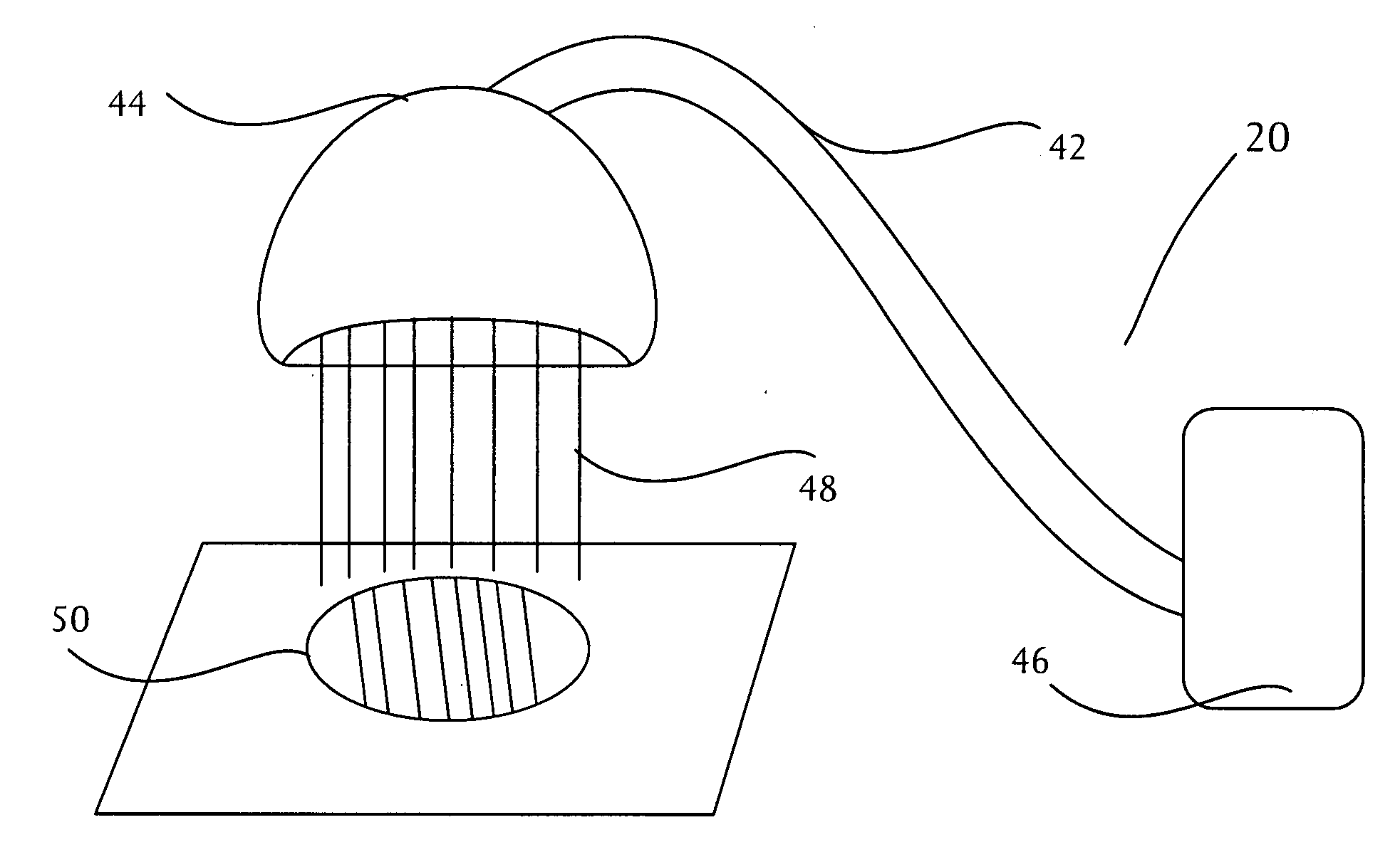
"The patent describes a device that uses ultra bright LEDs to remove tattoos and pigmented lesions. The device concentrates the output energy towards the skin area containing the tattoo, allowing it to penetrate the epidermis and go into the dermis where the tattoo is located. The energy output generated during a five minute period by a high bright LED display will be about 88 joules per square inch. This amount of energy is capable of damaging the tattoo ink molecules, resulting in effective tattoo removal. The device is placed on the tattooed area and exposed to the continuous light generated by the clustered ultra bright LEDs for a specific period of time. The average energy output in a 15 minute session is 480 Joules. The energy will break apart the bonds of the tattoo ink and cause it to be dispersed and absorbed into the body, fading or removing the tattoo. The method is safe and effective, with minimal damage to the skin."

Problems solved by technology

The absorption of the energy by the tattoo ink results in both heat generated in the ink molecules by molecular vibration and bond deformation by vibration, stretching and bending.

Method used


Image

  • Ultra bright LED induced tattoo removal
  • Ultra bright LED induced tattoo removal
  • Ultra bright LED induced tattoo removal

Examples


example 1

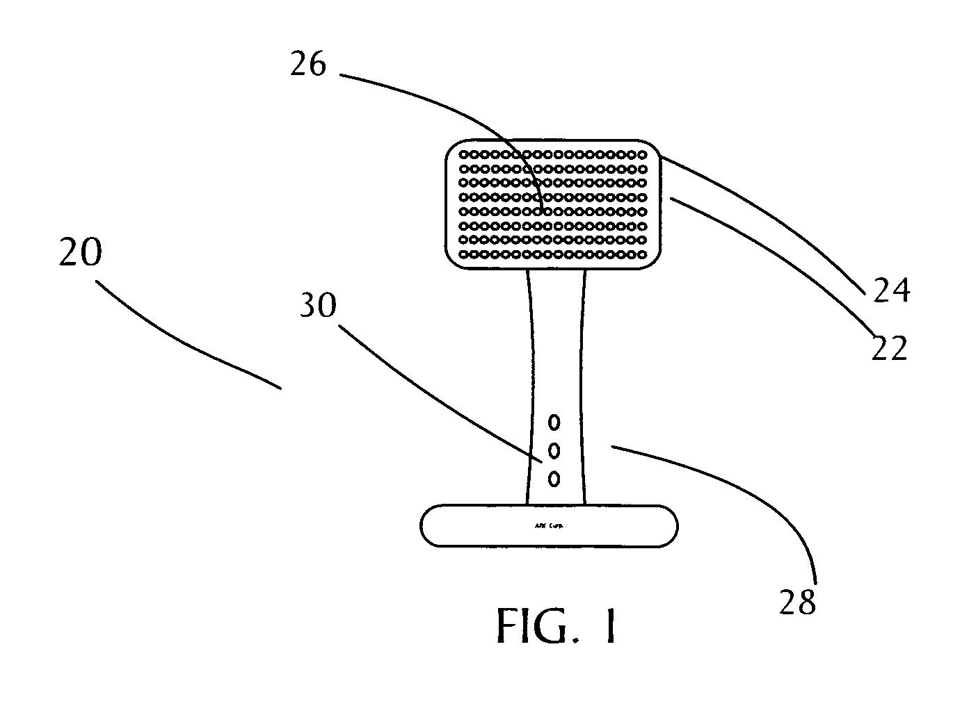
[0025]The operator places the apparatus approximately 1 to 2 inches above the tattooed area (See FIG. 5). The apparatus contains 120 ultra bright LEDs 26 clustered in twelve rows of ten LEDs each. The tattoo area is then exposed to the continuous light generated by the clustered ultra bright LEDs for 15 minutes. The average energy output, in this 15 minute session is 480 Joules. During this period of time, the light penetrates through the epidermis and into the dermal layer in which the tattoo resides. The absorption of the energy by the tattoo ink results in both heat generated in the ink molecules by molecular vibration and molecular bond deformation by vibration, stretching and bending. Thus, resulting in the tattoo being removed.

example 2

[0026]A thin layer of 10% to 15% of L-Arginine is applied directly to the tattoo area by the operator. The operator then places the apparatus approximately 1 to 2 inches above the tattooed area after L-arginine as been administered. The apparatus contains 120 ultra bright LEDs 26 clustered in twelve rows of ten LEDs each. The tattoo area is then exposed to the continuous light generated by the clustered ultra bright LEDs for 15 minutes. The average energy output, in this 15 minute session is 480 Joules. During this period of time, the light penetrates through the epidermis and into the dermal layer in which the tattoo resides. The absorption of the energy by the tattoo ink results in both heat generated in the ink molecules by molecular vibration and molecular bond deformation by vibration, stretching and bending. Thus, resulting in the tattoo being removed.

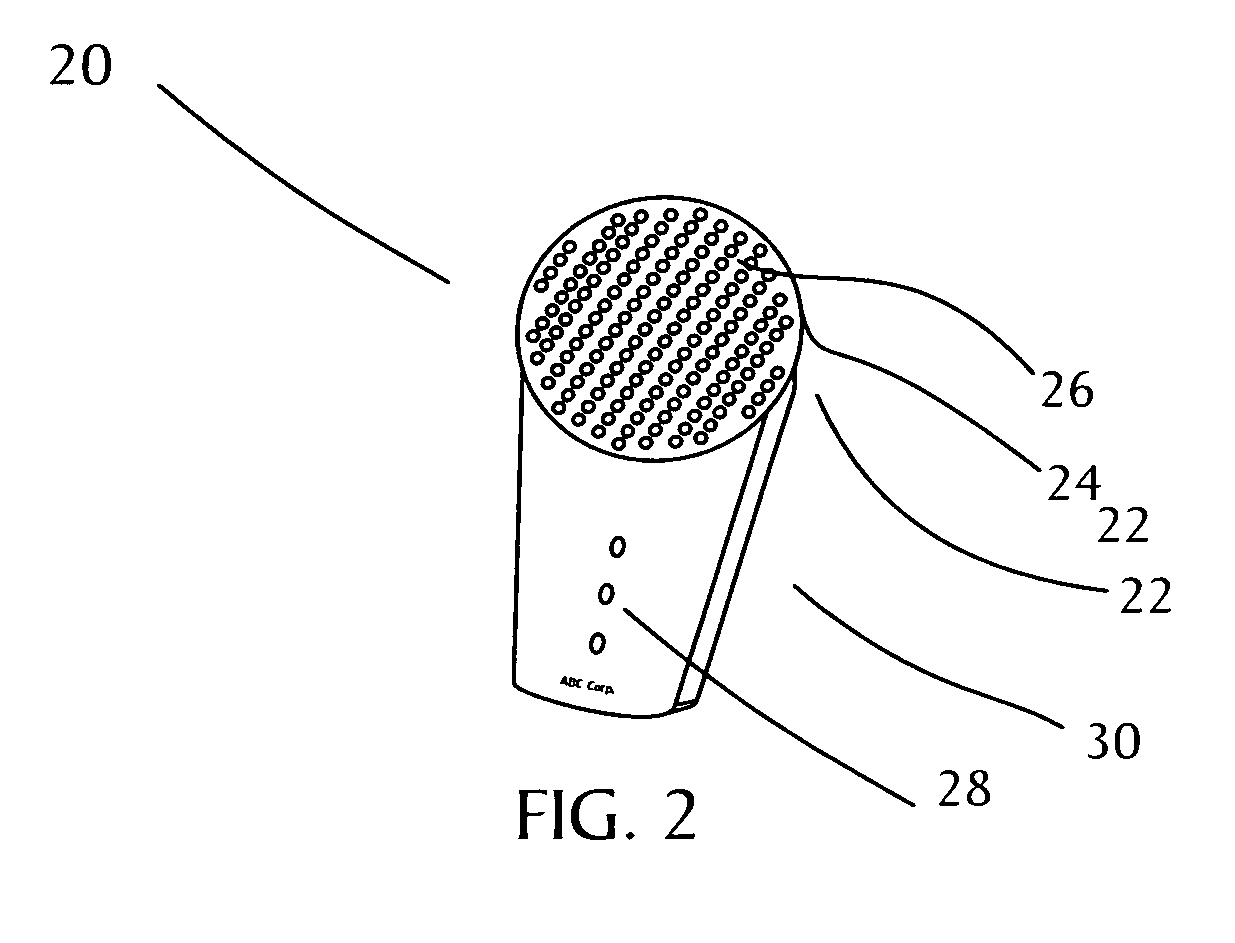
[0027]Referring to FIG. 2, a hand-held optical device 20 constructed in accordance with the present invention is illustrated. I...


PUM


Abstract

A device for removing tattoos is provided having ultra bright LEDs in a tight array to concentrate the output energy toward a skin area containing a tattoo. The output energy, such as, for a red color ultra bright LED, will be about 88 joules per square inch. The amount of energy emitted into the tattoo will penetrate the epidermis and into the dermis in which the tattoo is situated.A method of removing tattoos using an optical device is provided that has a panel which houses a plurality of ultra bright LEDs. The ultra bright LEDs clusters are configured to penetrate the outer skin layer epidermis without damaging the skin by overheating and enter the next layer of skin, the dermis, to destroy the ink for effective tattoo removal.

Description

RELATED APPLICATIONS[0001]This application claims the priority of provisional application Ser. No. 61 / 068,369, filed Mar. 7, 2008 and provisional application Ser. No. 61 / 941,173, filed Sep. 26, 2008.BACKGROUND OF THE INVENTION[0002]1. Field of the Invention[0003]This invention relates generally to removal of tattoos and other pigmented skin lesions without skin damage.[0004]2. Description of the Related Art[0005]A variety of medical procedures and techniques to remove tattoos are disclosed in the prior art. For example, dermabrasion has been used to remove tattoos, in which the skin is simply sliced off or abraded. This naturally produces scars. Often, pigments which lie in different skin layers are not removed along with the others. In addition to the scar, a dark shade from the remnants of the tattoo showing through remains. Another method involves the tangential excision and covering with a “split-skin graft”. The skin layer concerned is cut out under general anesthesia while it ...

Claims


Application Information

Patent Timeline
Patent Type & Authority Applications(United States)
IPC IPC(8): A61M35/00A61B18/18
CPCA61B18/203A61B2017/00769A61N2005/0652A61B2018/1807A61B2018/00452
Inventor PELLEGRINI, FRANK
Owner INREXREM
Learn More