Oil separator for blow-by gas

Active Publication Date: 2009-09-17
KOJIMA PRESS IND CO LTD +1
View PDF5 Cites 10 Cited by
  • Summary
  • Abstract
  • Description
  • Claims
  • Application Information

AI Technical Summary

Benefits of technology

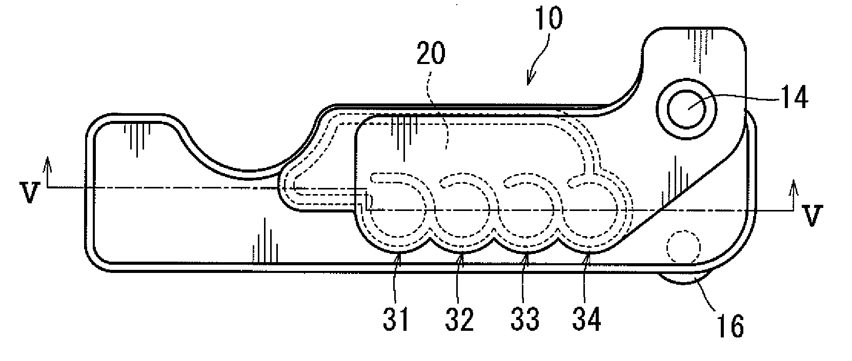
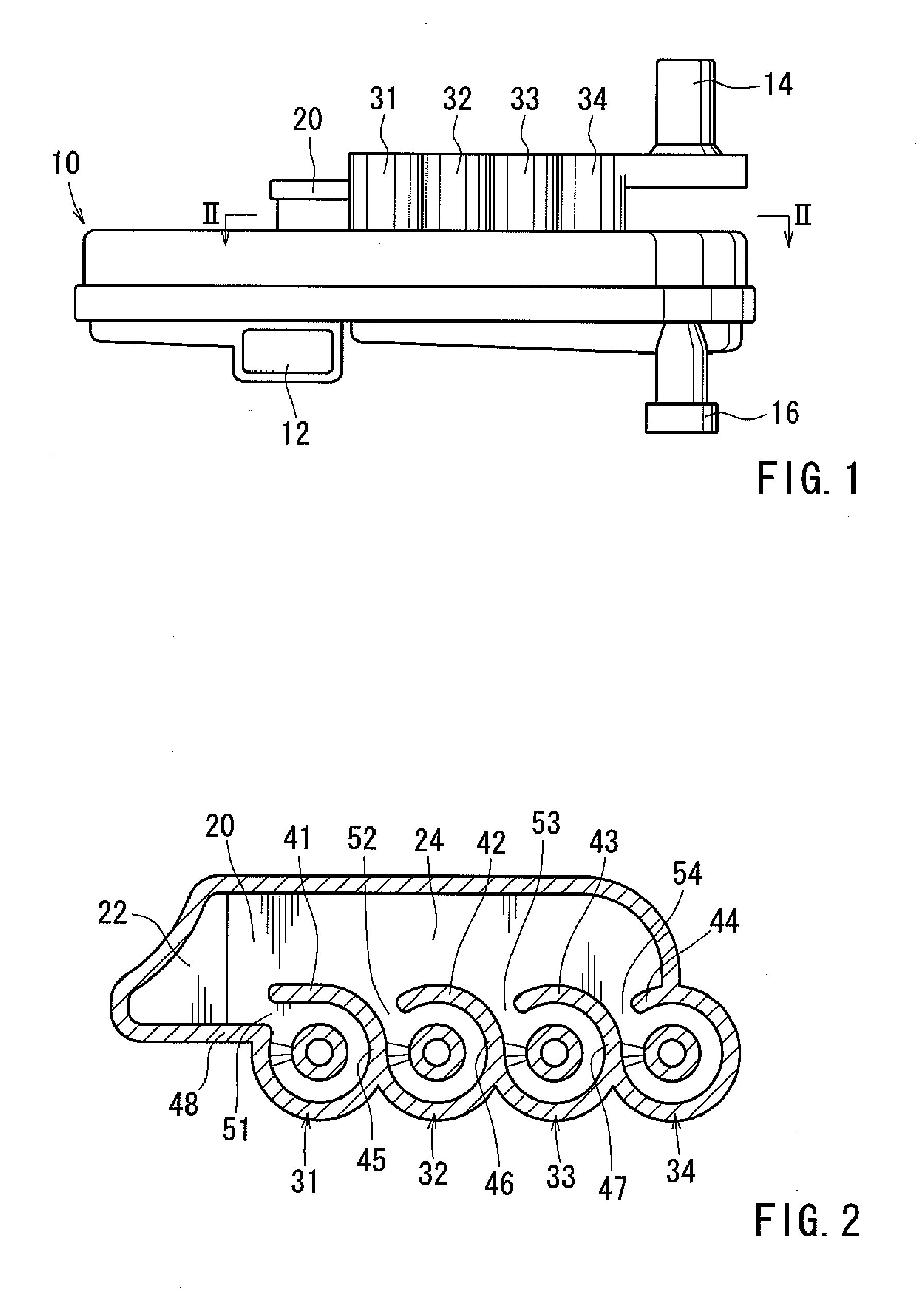
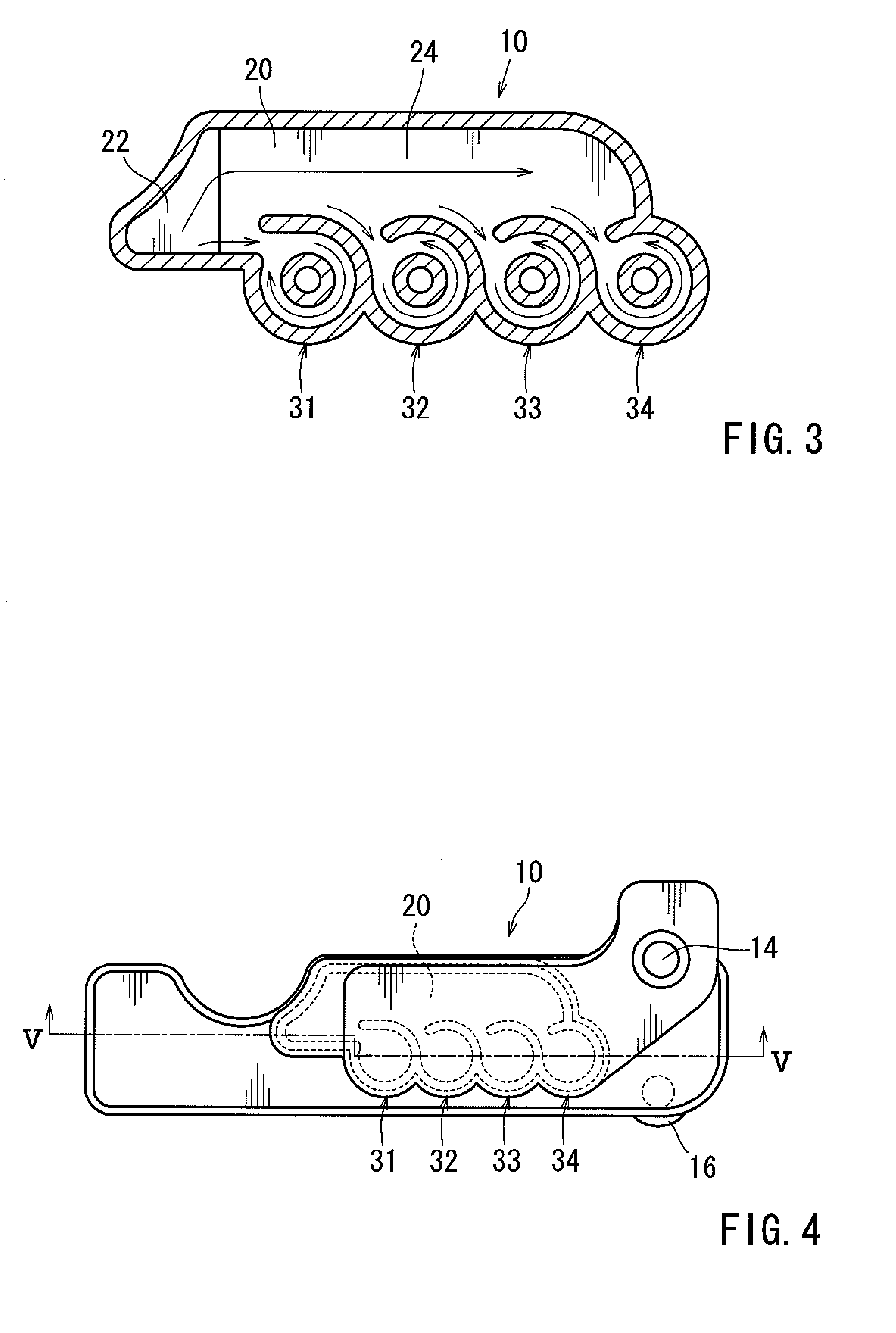
[0013]To provide an oil separator including multiple cones and having a simple structure and high trapping efficiency for oil mist. An oil separator can include multiple cones arranged in a line and a chamber for blow-by gas, which is formed in adjacent to the line of the cones, and arranged at an upper side surface of the cones, the chamber being provided with a flow-in port at a position in front of the line of the cones, in which upper outer peripheral walls of the cones at portions facing the chamber constitute partition walls provided with slits, which constitute inlets for the blow-by gas to enter the cones.

Problems solved by technology

Further, emission of the blow-by gas into the atmosphere causes air pollution.
In the previous described cone type oil separator configuration, a range of a flow rate of the blow-by gas, in which a cone can exert the best performance, is limited.
Another known oil separator has proposed a single cone in the oil separator, yet a problem arises such that the flow rate of the blow-by gas is low, resulting in a deteriorated trapping performance for the oil mist.
However, this method makes this configuration complicated, and leads to cost increase.
The blow-by gas hits against partitions of the flow channel, and hence a flow is likely to be disturbed.
Therefore, the oil separator according to this configuration has a structure disadvantageous for forming the swirling flow in the cones, and an oil mist trapping efficiency of the cones is low or inefficient.

Method used


Image

  • Oil separator for blow-by gas
  • Oil separator for blow-by gas
  • Oil separator for blow-by gas

Examples


Embodiment Construction

[0020]Each of the additional features and teachings disclosed above and below may be utilized separately or in conjunction with other features and teachings to provide an oil separator for blow-by gas. Representative examples of the present invention, which examples utilize many of these additional features and teachings both separately and in conjunction with one another, will now be described in detail with reference to the attached drawings. This detailed description is merely intended to teach a person of skill in the art further details for practicing preferred aspects of the present teachings and is not intended to limit the scope of the invention. Only the claims define the scope of the claimed invention. Therefore, combinations of features and steps disclosed in the following detailed description may not be necessary to practice the invention in the broadest sense, and are instead taught merely to particularly describe representative examples of the invention. Moreover, vari...


PUM


Abstract

To provide an oil separator including multiple cones and having a simple structure and high trapping efficiency for oil mist. An oil separator can include multiple cones arranged in a line and a chamber for blow-by gas, which is formed in adjacent to the line of the cones, and arranged at an upper side surface of the cones, the chamber being provided with a flow-in port at a position in front of the line of the cones, in which upper outer peripheral walls of the cones at portions facing the chamber constitute partition walls provided with slits, which constitute inlets for the blow-by gas to enter the cones.

Description

[0001]This application claims priority to Japanese patent application serial number 2008-64023, the contents of which are incorporated herein by reference.BACKGROUND OF THE INVENTION[0002]1. Field of the Invention[0003]The present invention relates to an oil separator for blow-by gas, and more particularly, to an oil separator for trapping oil mist in blow-by gas generated in an engine crankcase of an internal combustion engine such as an automobile engine, the oil separator being structured so that multiple cones trap the oil mist.[0004]2. Description of the Related Art[0005]In an internal combustion engine such as an automobile engine, at a time of operation thereof, blow-by gas leaks out from a gap between a piston ring and a cylinder wall. Further, emission of the blow-by gas into the atmosphere causes air pollution. Accordingly, by using a so-called positive crankcase ventilation (PCV) system provided inside the internal combustion engine, the blow-by gas is returned to an inta...

Claims


Application Information

Patent Timeline
IPC IPC(8): F01M13/04
CPCF01M13/04F01M2013/0427F01M2013/0066
Inventor TANAKA, TOSHIMITSUIKEDA, JUNOKADA, NAOYA
Owner KOJIMA PRESS IND CO LTD
Why Eureka
Try Eureka