Bridgeless pfc circuit for crm and controlling method thereof

Active Publication Date: 2009-09-17
DELTA ELECTRONICS INC
View PDF4 Cites 52 Cited by
  • Summary
  • Abstract
  • Description
  • Claims
  • Application Information

AI Technical Summary

Benefits of technology

[0010]It is therefore an object of the present invention to provide a method measuring a combined voltage of two inductor auxiliary windings to realize the measurement of the zero-crossing current of the inductor so as to control the DBPFC to work under the CRM. The controlling method does not need to measure the

Problems solved by technology

In the conventional boost PFC circuits, the rectifying bridge loss becomes one of the main losses of the switching mode power supply.
The inductor current signal is easy to be interfered by the noise when the amplitude of inductor current is quite small such that the t

Method used


Image

  • Bridgeless pfc circuit for crm and controlling method thereof
  • Bridgeless pfc circuit for crm and controlling method thereof
  • Bridgeless pfc circuit for crm and controlling method thereof

Examples


Embodiment Construction

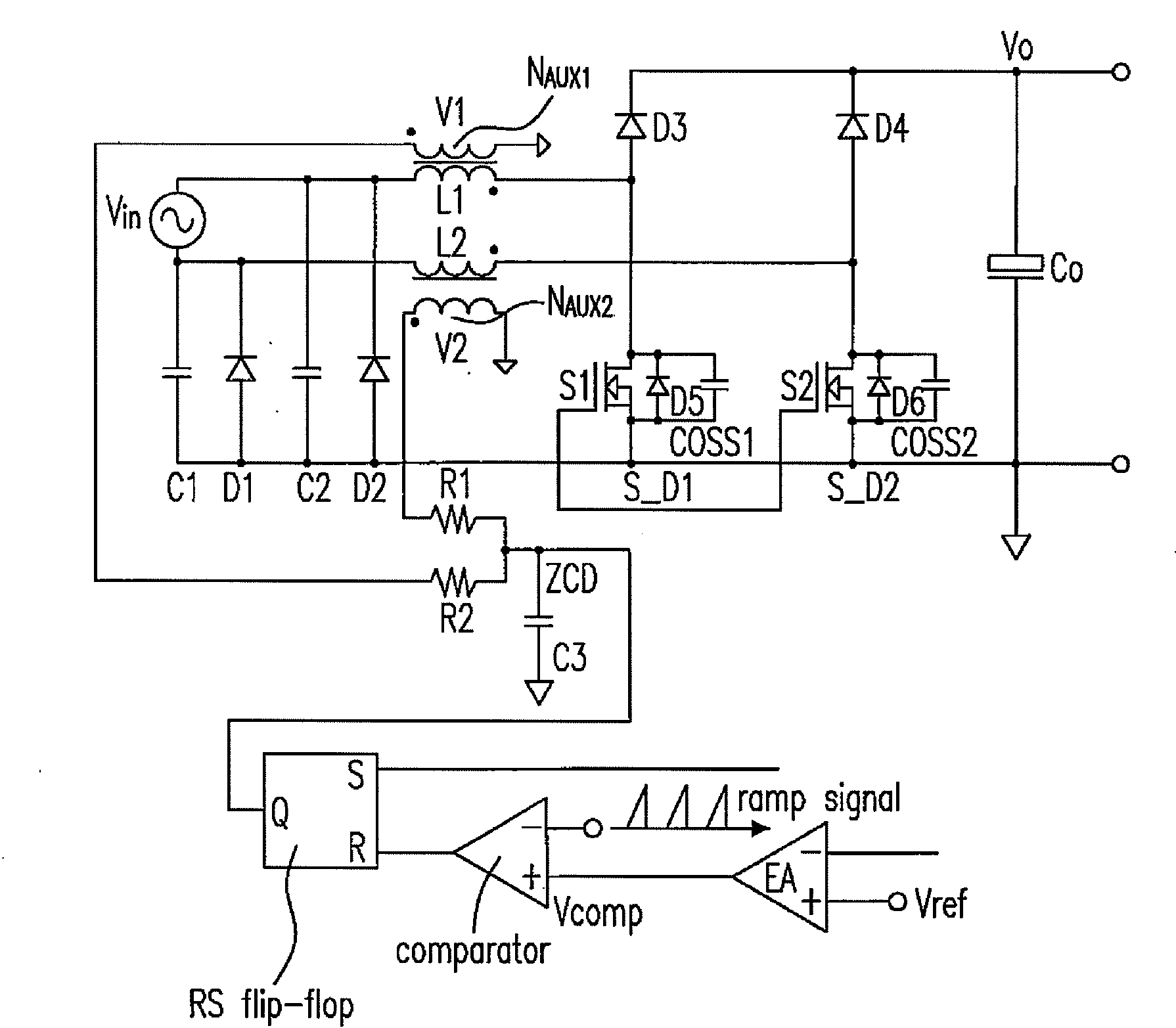
[0040]In the dual boost PFC circuit as shown in FIGS. 4(a)-4(b), although at each moment the two inductors are having currents flowing through simultaneously, one inductor voltage is clamped at the conduction voltage drop of the diode D1 or the diode D2 in the circuit when another inductor is implemented as a boost inductor. Due to that this conduction voltage drop is quite small, the voltage amplitude of the auxiliary winding is approximately zero, while the other inductor is under a boost mode. According to this feature, the method for measuring the auxiliary winding voltage of the boost inductor as shown in FIG. 3 could be employed to realize CRM controlling, that is to accumulate the voltages sensed by the two auxiliary windings through two resistors having the same resistance R1 and R2.

[0041]As shown in FIG. 8, it is a schematic circuit diagram of a dual boost PFC circuit employing two auxiliary windings to realize the CRM controlling according to the preferred embodiment of th...


PUM


Abstract

The configurations of a bridgeless PFC circuit system and a controlling method thereof are provided. The proposed system includes a bridgeless PFC circuit having a first and a second input terminals, a first switch having a first terminal, a first inductor having a first terminal coupled to the first input terminal and a second terminal coupled to the first terminal of the first switch, and a second inductor having a first terminal coupled to the second input terminal, a first auxiliary winding coupled to the first inductor and generating a first sensing signal, and a second auxiliary winding coupled to the second inductor and generating a second sensing signal, wherein the first and the second sensing signals are used to generate an inductor current sensing signal controlling the switching of the first switch accordingly.

Description

FIELD OF THE INVENTION[0001]The present invention relates to a bridgeless power factor correction (PFC) circuit for a CRM (critical conduction mode) and a controlling method thereof, which can be employed to solve the controlling problem of the CRM of the PFC circuit.BACKGROUND OF THE INVENTION[0002]In the conventional boost PFC circuits, the rectifying bridge loss becomes one of the main losses of the switching mode power supply. Following the requirements regarding the convention efficiency are improved, the bridgeless boost topology deriving from the conventional boost PFC circuit has gradually become the focus of the R&D. The bridgeless boost topology omits the rectifying bridge in the front stage of the boost PFC circuit, decreases the loss of a diode, and increases the efficiency. And a dual boost PFC (DBPFC) circuit belongs to a kind of bridgeless boost topologies (please refer to FIG. 1). In FIG. 1, the bridgeless PFC circuit receives the input voltage Vin, generates the out...

Claims


Application Information

Patent Timeline
IPC IPC(8): G05F1/70
CPCG05F1/70Y02B70/126H02M1/4208Y02B70/10Y02P80/10H02M1/0085
Inventor SUI, LUBOJIN, HONGYUANGAN, HONGJIAN
Owner DELTA ELECTRONICS INC
Why Eureka
Try Eureka