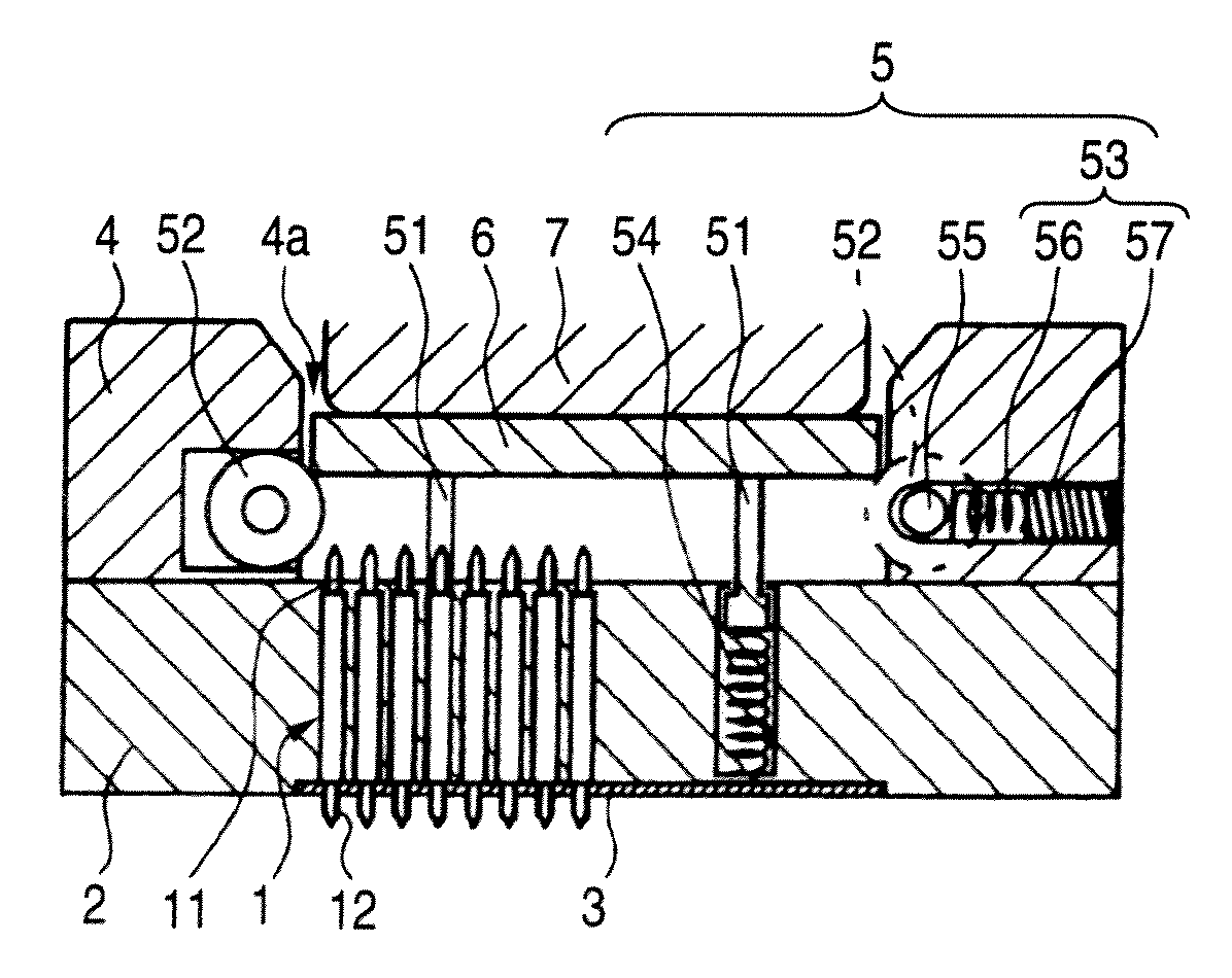
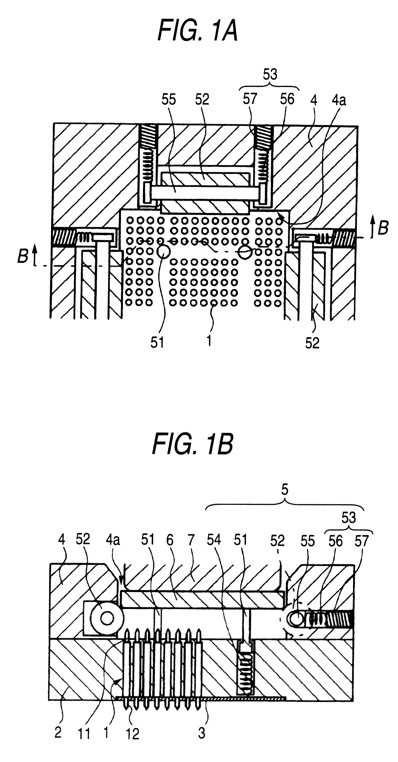
[0011]Specifically, the centering mechanism includes: support posts, which provisionally support the device to be inspected, and which can be moved up and down with a load; roller guides, provided at respective edges of the opening of the device guide in such a manner that at least parts of the roller guides are respectively exposed to the opening and the roller guides have rotation shafts which are substantially parallel to the edges; and pressing means for enabling the roller guides to move in a direction perpendicular to the edges. Therefore, the centering of the device to be inspected can be performed while the rotating rollers rotate, and hence, it is possible to prevent occurrence of abrasion by
rubbing and generation of
static electricity. The
phrase “substantially parallel” means such a
degree of parallelism that the centering can be conducted, even though the roller may get in touch with an edge of the device to be inspected.
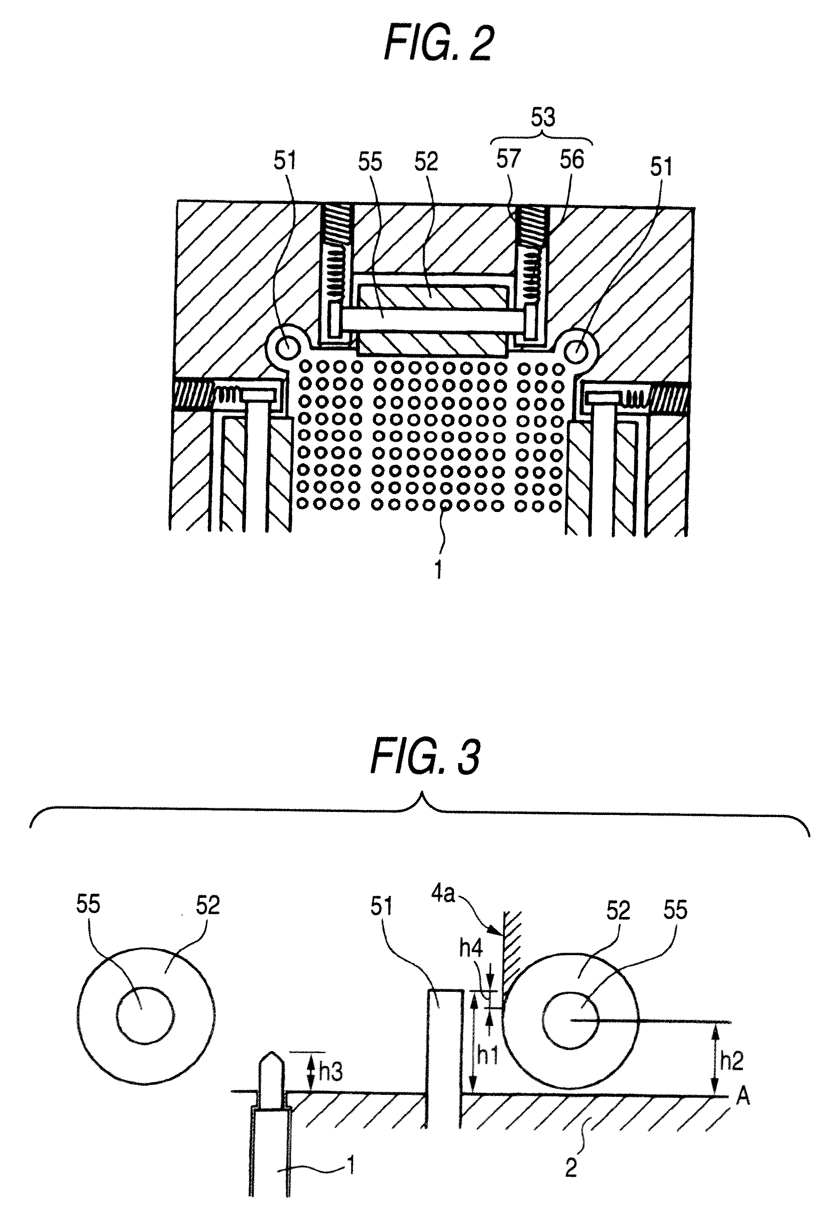
[0012]The probes include contact probes in which tip ends of pins at least at a side opposed to the device to be inspected can be moved up and down by springs, and a height of the tip ends of the pins of the contact probes freely projected from a surface of the support block is h3, a height of center positions of roller shafts of the roller guides from the surface of the support block is h2, a height of top faces of the support posts from the support block in a state where no load is applied to the support posts is h1, and the support posts, the roller guides and the probes are provided so as to satisfy the relation h1>h2>h3. As the results, the centering can be completely performed, when the device to be inspected has come to the center position of the roller shafts of the roller guides, and the device to be inspected is brought into contact with the contact probes in a thus centered state thereby to be set on the socket for inspection instantly. Therefore, reliable contact between the electrode terminals of the device to be inspected and the probes can be obtained.
[0013]Further, position detecting means for detecting the position of the device to be inspected with respect to the opening are further provided, and the pressing means is provided with adjusting means which can adjust the center position of the device to be inspected detected by the position detecting means so as to correspond to the center position of the opening. Therefore, even though the forces of the pressing means which are respectively provided on the opposed edges are not completely equal in a state before the centering starts, the centering can be always conducted, by adjusting the pressing forces. in case where the pressing means which are respectively provided on the opposed edges are set to have the equal forces, in advance, and the device to be inspected can freely move, the centering can be automatically conducted, even though the position of the device to be inspected with respect to the opening in the device guide is not detected every time.
[0015]According to the socket for inspection of the invention, the centering mechanism for the device to be inspected is provided so that the center of the device to be inspected is positioned at the center of the opening in the device guide. Therefore, even though there is a gap between the opening in the device guide and the outer periphery of the device to be inspected, it is always possible to set the device to be inspected at the center of the opening. On the other hand, as the result of extensive researches by the inventor, it has been confirmed that displacement of the electrode terminals with respect to the center position of the device to be inspected is within a range of 0.15 mm in
diameter (displacement of the center positions of the electrode terminals is 0.075 mm), and defective contact between the electrode terminals and the probes is eliminated, by aligning the center position of the device to be inspected with the center position of the opening in the device guide, even though a
pitch of the electrode terminals is less than 0.4 mm.
[0016]Further, because the centering mechanism includes the support posts which support the device to be inspected provisionally, the roller guides provided at respective edges of the opening, and the pressing means for pressing the roller guides in a direction perpendicular to the edges, when the device to be inspected is mounted on the support posts and pushed down as it is, the device to be inspected is brought into contact with the roller guides, and positional adjustment is performed, while the roller guides rotate. In this case, in case where the pressing forces of the roller guides on the opposed two edges are equal, the centering can be automatically performed. On the other hand, in case where the pressing forces on the opposed edges are not equal, it is possible to detect the positional relation of the device to be inspected with respect to the opening, using the position detecting means such as a
microscope, an image recognizing device, and to conduct the centering by minutely adjusting the positions of the roller guides, if there is any deviation. Then, by pushing down the device to be inspected in this state so as to be brought into contact with the surface of the support block, it is possible to set the device to be inspected on the support block by centering. As the results, the static
electricity due to friction is unlikely to occur in the device to be inspected, and at the same time, abrasion of the socket for inspection can be restrained.
[0017]Further, the contact probes in which the tip ends of the pins (plungers) move up and down by means of the springs are employed as the probes, and provided that the heights of the tip ends of the pins in a state where the device to be inspected is not mounted, the height of the center positions of the roller shafts of the roller guides, and the highest position of the support posts from the support block in a state where no load is applied are respectively represented as h3, h2, and h1, the support posts, the roller guides and the probes are provided so as to satisfy the relation h1>h2>h3. In this case, the aforesaid adjustment of the centering can be conducted, before the device to be inspected comes into contact with the contact probes. At the same time, by removing the load for pressing the device to be inspected after the inspection has finished, the device to be inspected is naturally lifted up by the support posts, and can be picked up in a
free state, without receiving the pressing force from the roller guides. Therefore, it is possible to very easily take out the device to be inspected. At the same time, reliability of the inspection is extremely enhanced by
elimination of occurrence of the static
electricity due to friction when the device to be inspected is detached, and damage of the socket for inspection due to abrasion.

