Endoscope Assembly and Method of Performing a Medical Procedure

a technology of endoscope and endoscope, which is applied in the field of endoscope assembly and a medical procedure, can solve the problems of preventing the instrument from reaching, adding discomfort, complications, and risks to the patient, and achieving the effect of convenient handling

Inactive Publication Date: 2009-09-17
PSIP LLC
View PDF105 Cites 160 Cited by
  • Summary
  • Abstract
  • Description
  • Claims
  • Application Information

AI Technical Summary

Benefits of technology

[0007]This problem associated with prior art endoscopes is overcome by the present invention. In one preferred embodiment, the present invention provides (1) an instrument that can reach areas that are difficult or impossible to reach with an instrument extending through a channel in the main endoscope and (2) possibly a second, auxiliary camera that presents an image from a different point-of-view and enables viewing of areas not viewable by the endoscope's main camera. This arrangement of cameras may provide different views of an area, and this arrangement of instruments may allow the instruments to reach an area from different angles. In another preferred embodiment, the second camera and instrument may be integrated to allow, for example, easy handling and cooperation between the second camera and the instrument.

Problems solved by technology

Repositioning and movement of the endoscope prolongs the procedure and causes added discomfort, complications, and risks to the patient.
Additionally, in an environment such as the lower gastro-intestinal tract, flexures, tissue folds and unusual geometries of the organ may prevent the endoscope's camera from viewing the “hidden” areas of the organ and prevent the instrument from reaching the “hidden” areas (or at least make it difficult for the instrument to reach these same areas).
The inability to view the “hidden” areas may cause a potentially malignant polyp to be missed, and the inability (or difficulty) to reach the “hidden” areas may require an expensive and intrusive procedure to remove the polyp (or at least prolong the procedure to use the endoscope to remove the polyp).
Furthermore, it is difficult to optimally remove a potentially malignant polyp using a conventional endoscope.
The difficulty to see and reach a polyp often results in only partial removal of the polyp or removal of normal tissues in addition to the polyp, which increases the risk of the procedure to the patient.
With a conventional endoscope, this is difficult to accomplish if the polyp is in a “hidden” area, because the inability or difficulty to see how the snare is placed round the polyp.

Method used


Image

  • Endoscope Assembly and Method of Performing a Medical Procedure
  • Endoscope Assembly and Method of Performing a Medical Procedure
  • Endoscope Assembly and Method of Performing a Medical Procedure

Examples


Embodiment Construction

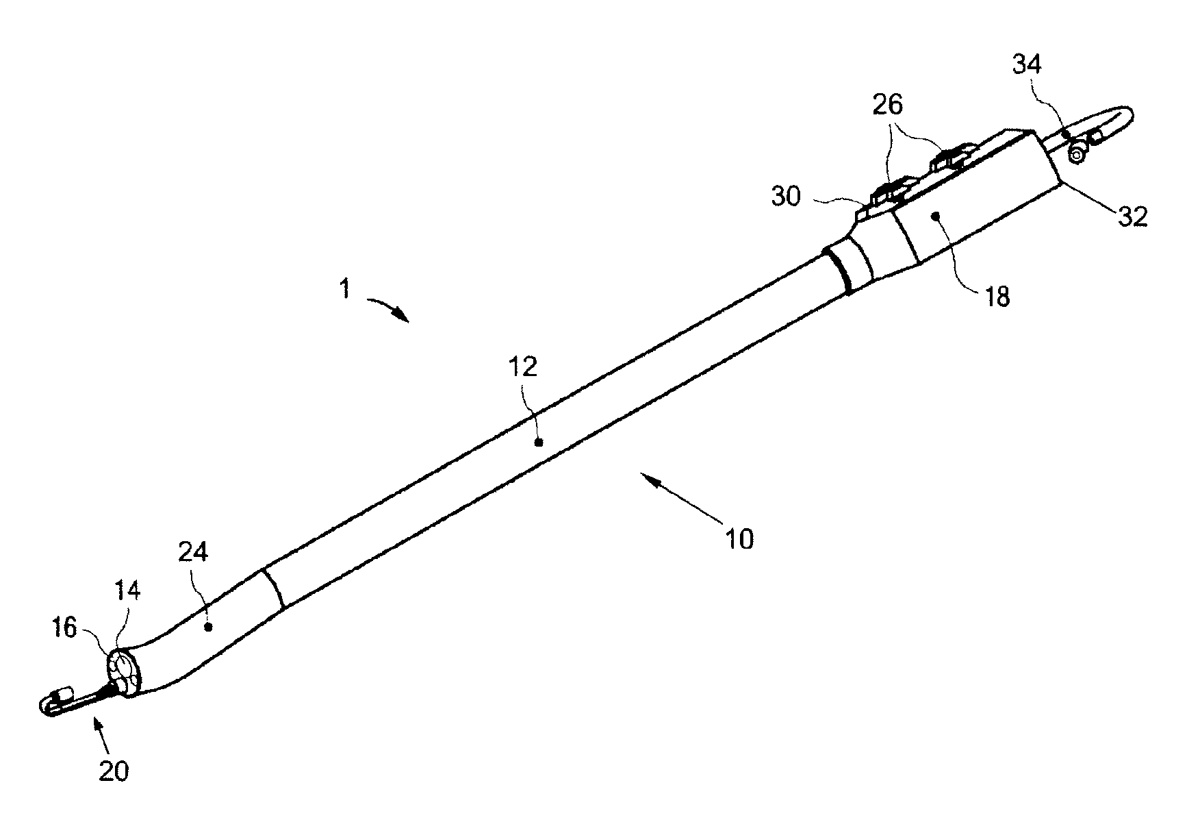
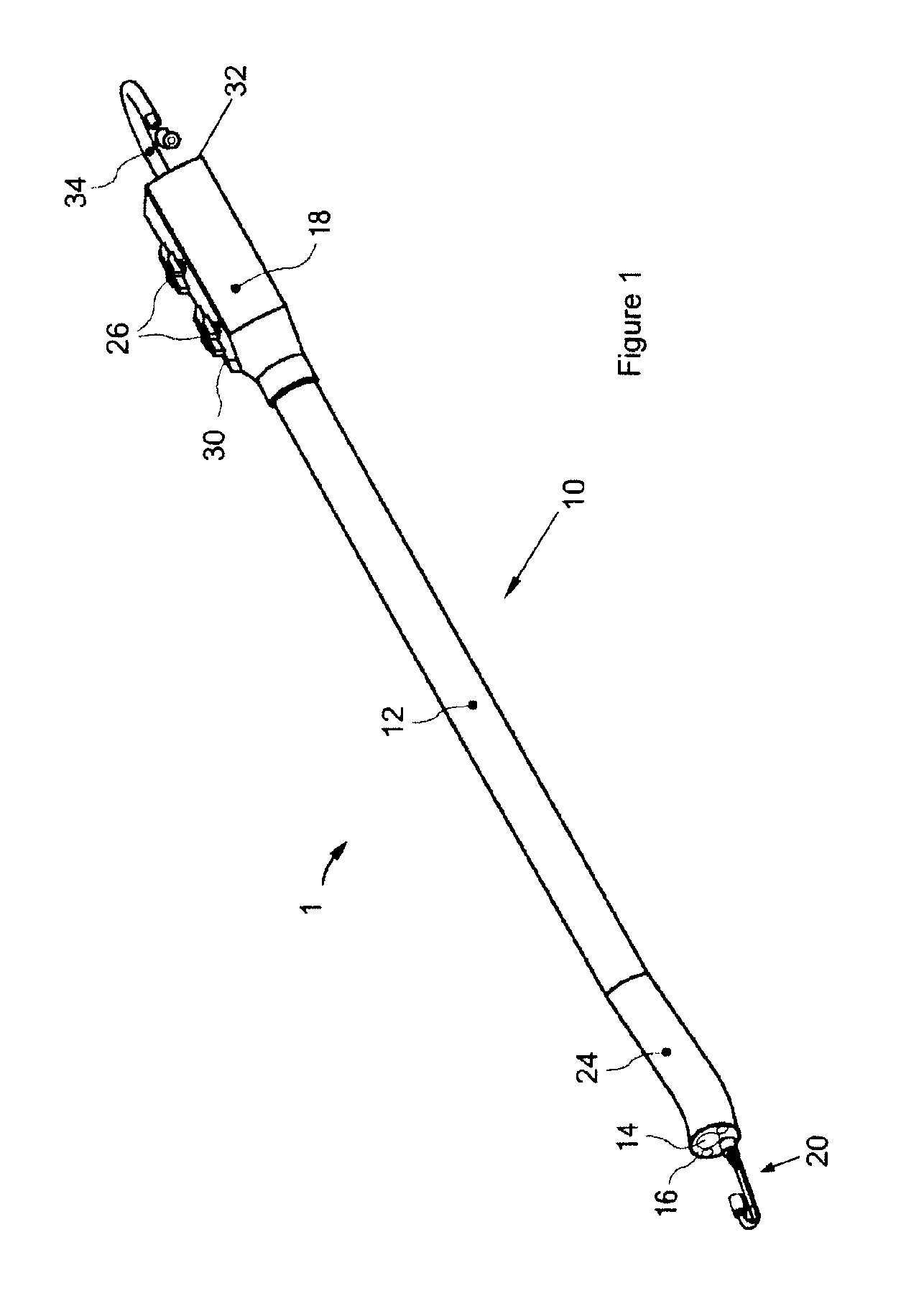
[0048]FIG. 1 illustrates a first exemplary endoscope system 1 of the present invention. This endoscope system 1 can be used in a variety of medical procedures in which imaging of a body tissue, organ, cavity or lumen is required. The types of procedures include, for example, anoscopy, arthroscopy, bronchoscopy, colonoscopy, cystoscopy, EGD, laparoscopy, and sigmoidoscopy.

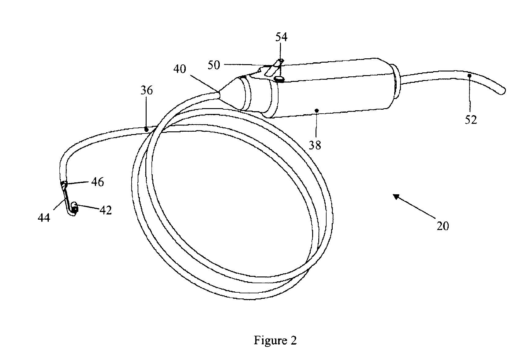
[0049]The endoscope system 1 of FIG. 1 includes a main endoscope 10 and a minor endoscope 20. The main endoscope 10 includes an insertion tube 12, a main imaging device 14 disposed at the distal end 16 of the insertion tube 12 (FIG. 3), and a control handle 18 connected to the proximal end of the insertion tube 12. The minor endoscope 20 is disposed at the distal and proximal ends of the insertion tube 12 and inside the insertion tube 12.

[0050]In the main endoscope 10, the insertion tube 12 may be detachable from the control handle 18 or may be integrally formed with the control handle 18. The diameter, length and f...


PUM


Abstract

An endoscope assembly includes (1) an endoscope that includes a tubular body, a retrograde-viewing imaging device disposed at a distal end region of the tubular body, and a channel extending through the tubular body; and (2) an instrument extending through the channel of the endoscope and exits from a distal opening of the channel.

Description

[0001]This application claims the benefit of U.S. Provisional Patent Application No. 60 / 979,367, filed Oct. 11, 2007, the entire disclosure of which is incorporated herein by reference.[0002]This application is a continuation-in-part application of U.S. patent application Ser. No. 11 / 672,020, filed Feb. 6, 2007, the entire disclosure of which is incorporated herein by reference.TECHNICAL FIELD OF THE INVENTION[0003]The present invention relates to an endoscope assembly and a method of performing a medical procedure.BACKGROUND OF THE INVENTION[0004]An endoscope is a medical device comprising a flexible tube and a camera mounted on the distal end of the tube. The endoscope is insertable into an internal body cavity through a body orifice or a surgical incision to examine the body cavity and tissues for diagnosis. The tube of the endoscope has one or more longitudinal channels, through which an instrument can reach the body cavity to take samples of suspicious tissues or to perform oth...

Claims


Application Information

Patent Timeline
Patent Type & Authority Applications(United States)
IPC IPC(8): H04N7/18
CPCA61B1/00096A61B1/00179A61B1/00181A61B1/0051A61B1/0058A61B1/0125A61M25/0147A61B1/053A61B1/0615A61B18/08A61B18/20A61B2018/00577A61B1/018
Inventor BAYER, LEX
Owner PSIP LLC
Why Eureka
Try Eureka