Eureka AIR delivers breakthrough ideas for toughest innovation challenges, trusted by R&D personnel around the world.

Discharge lamp lighting device, control method thereof, and projector

a technology of discharge lamp and lighting device, which is applied in the direction of electric variable regulation, process and machine control, instruments, etc., can solve the problems of scroll noise, flickering in which the discharge start position is suddenly changed, and the brightness of the discharge lamp is suddenly changed

Active Publication Date: 2009-09-17
ASSIGNEE NAME SEIKO EPSON
View PDF1 Cites 18 Cited by
  • Summary
  • Abstract
  • Description
  • Claims
  • Application Information

AI Technical Summary

Benefits of technology

"The invention provides a discharge lamp lighting device that can select the frequency of discharge-lamp driving AC current and control the duty ratio and interval current of the DC current to suppress scroll noise. This allows for the selection of the most suitable frequency for the discharge-lamp driving AC current, resulting in improved performance and reliability of the device. The control method includes a duty ratio control process and an interval current control process that adjust the current value of the DC current at predetermined intervals during the polarity inversion of the discharge-lamp driving AC current. This results in a more stable and efficient operation of the device. The invention also provides a projector comprising this discharge lamp lighting device."

Problems solved by technology

In the discharge lamps, a shape of an electrode is changed by dissipation of the electrode due to the electric discharge and thus flickers in which a discharge start position is suddenly changed may occur.
When the flickers occur, the brightness of the discharge lamps is suddenly changed greatly, which is not desirable.
When the discharge lamp and the liquid crystal panel are combined, the periodical changes in brightness interfere with each other, thereby causing a scroll noise.
For example, in the above-mentioned example, the change in brightness of the discharge lamp of 156 Hz and the change in brightness of the liquid crystal panel of 150 Hz interfere with each other, thereby causing a scroll noise of 6 Hz.

Method used


Image

  • Discharge lamp lighting device, control method thereof, and projector
  • Discharge lamp lighting device, control method thereof, and projector
  • Discharge lamp lighting device, control method thereof, and projector

Examples


Embodiment Construction

[0036]Hereinafter, exemplary embodiments of the invention will be described in detail with reference to the accompanying drawings. The embodiments to be described below are not intended to improperly define the details of the invention described in the appended claims. It cannot be said that constituent elements to be described below are necessary constituent elements of the invention.

1. Optical System of Projector

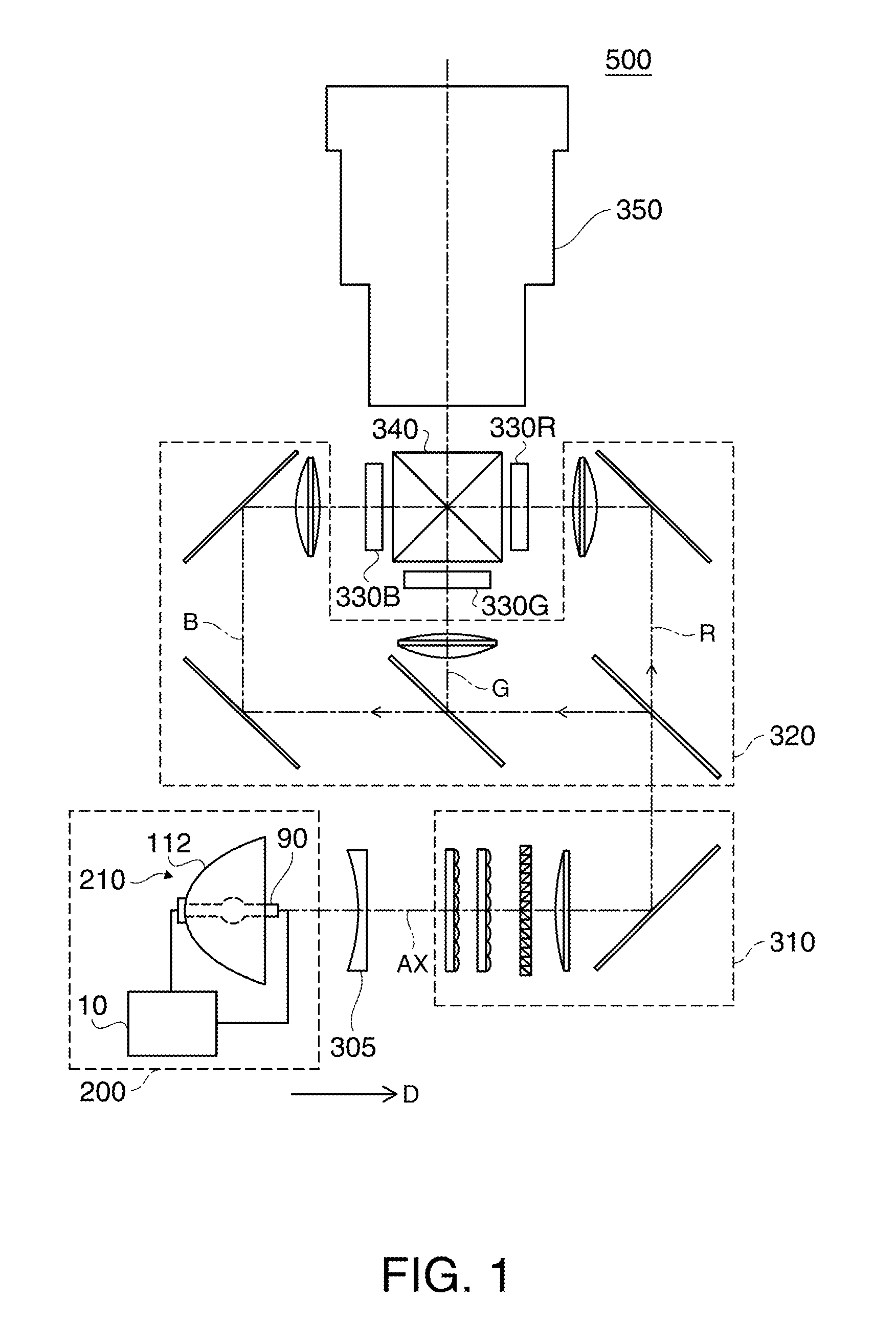
[0037]FIG. 1 is a diagram illustrating a projector 500 according to an embodiment of the invention. The projector 500 includes a light source device 200, a collimating lens 305, an illumination optical system 310, a color-separating optical system 320, three liquid crystal light valves 330R, 330G, and 330B, a cross dichroic prism 340, and a projection optical system 350.

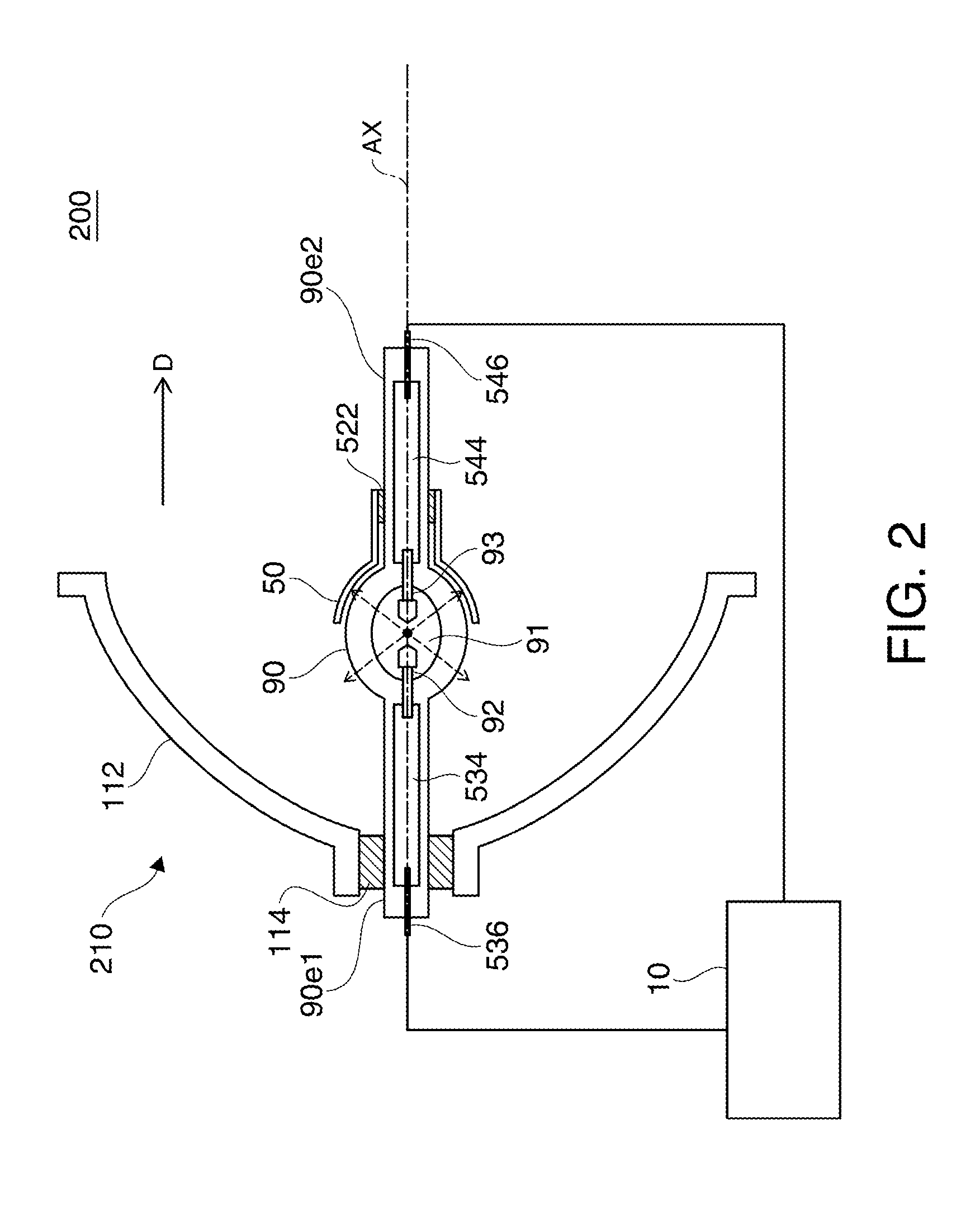
[0038]The light source device 200 includes a light source unit 210 and a discharge lamp lighting device 10. The light source unit 210 includes a primary reflecting mirror 112, a secondary reflecting mirror ...


PUM


Abstract

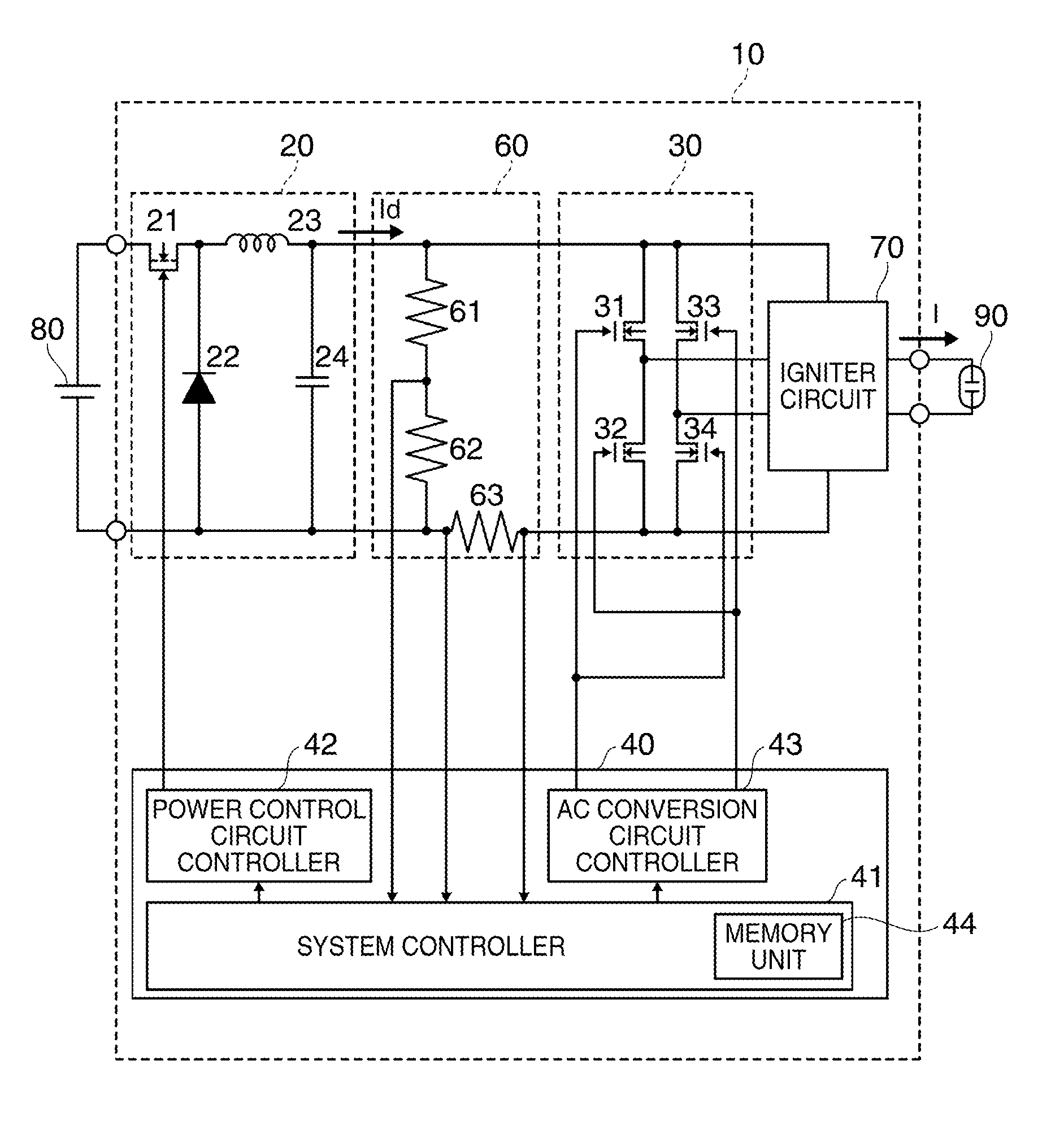
A discharge lamp lighting device includes: a power control circuit outputting DC current; an AC conversion circuit being supplied with the DC current and generating and outputting discharge-lamp driving AC current by inverting the polarity of the DC current at a predetermined time; and a control unit performing a duty ratio control process of controlling a duty ratio on the basis of a polarity inversion time of the discharge-lamp driving AC current on the AC conversion circuit and performing an interval current control process of controlling a current value of the DC current every polarity inversion time interval on the power control circuit. Here, the control unit performs the interval current control process so as to control a difference between an average value and a maximum value of the DC current of each polarity inversion time interval on the basis of a difference between the duty ratio and a predetermined reference duty ratio.

Description

BACKGROUND[0001]1. Technical Field[0002]The present invention relates to a discharge lamp lighting device, a control method thereof, and a projector.[0003]2. Related Art[0004]Electric-discharge lamps (hereinafter, referred to as discharge lamp) such as high-pressure mercury lamps or metal halide lamps are used as a light source of projectors. In the discharge lamps, a shape of an electrode is changed by dissipation of the electrode due to the electric discharge and thus flickers in which a discharge start position is suddenly changed may occur. When the flickers occur, the brightness of the discharge lamps is suddenly changed greatly, which is not desirable.[0005]To solve this problem, a discharge lamp driving method is known in which the flickers are suppressed by raising a current value of the AC driving current in a second half of a half cycle of discharge-lamp driving AC current (see JP-T-10-501919).[0006]However, in the driving method disclosed in JP-T-10-501919, the current va...

Claims


Application Information

Patent Timeline
Patent Type & Authority Applications(United States)
IPC IPC(8): G03B21/00H05B41/16
CPCG03B21/00Y02B20/202H05B41/2928H05B41/2886G03B21/005Y02B20/00
Inventor TANAKA, KAZUHIROYAMAUCHI, KENTAROTERASHIMA, TETSUOTAKEZAWA, TAKESHI
Owner ASSIGNEE NAME SEIKO EPSON
Why Eureka
Eureka Blog
Learn More