Laser frequency stabilizing device, method and program

a technology of laser frequency stabilization and laser frequency, which is applied in the direction of laser details, optical resonator shape and construction, electrical equipment, etc., can solve the problems of deteriorating measurement accuracy, and affecting the stability of the devi

Inactive Publication Date: 2009-09-17
MITUTOYO CORP
View PDF13 Cites 14 Cited by
  • Summary
  • Abstract
  • Description
  • Claims
  • Application Information

AI Technical Summary

Benefits of technology

[0011]With such the configuration, the laser frequency stabilizing device can stabilize the frequency without modulating the resonant cavity length.

Problems solved by technology

In a word, in the prior art, the influence of the modulation associated with the measurement of the saturated absorption signal may deteriorate the measurement accuracy and so forth as a problem.
The configuration uses an expensive optical element, which elevates the cost.

Method used


Image

  • Laser frequency stabilizing device, method and program
  • Laser frequency stabilizing device, method and program
  • Laser frequency stabilizing device, method and program

Examples


Embodiment Construction

[0018]A laser frequency stabilizing device according to an embodiment of the present invention will now be described with reference to the drawings.

(Configuration of Laser Frequency Stabilizing Device According to Present Embodiment)

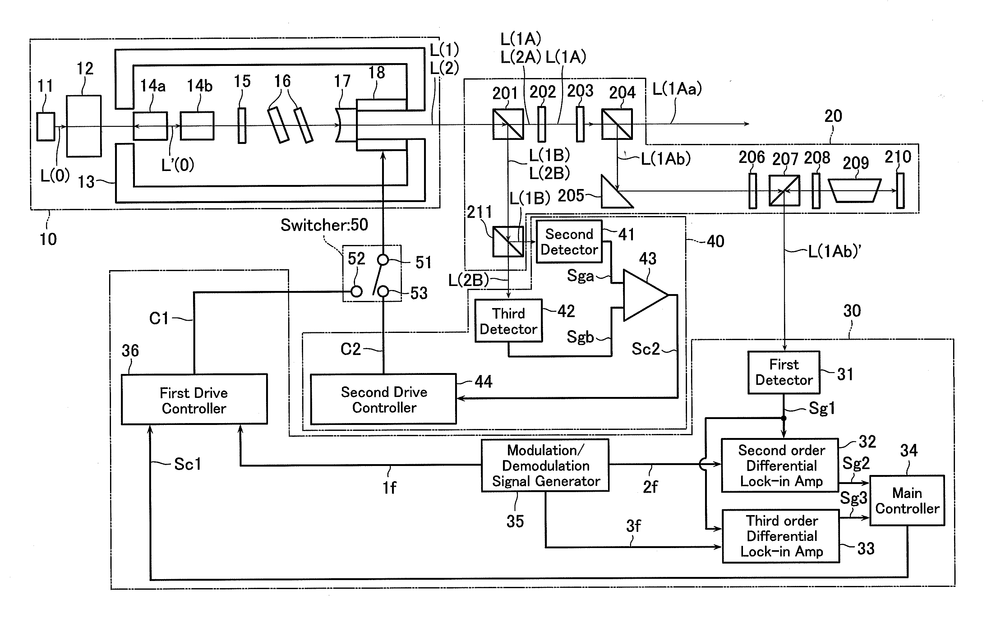
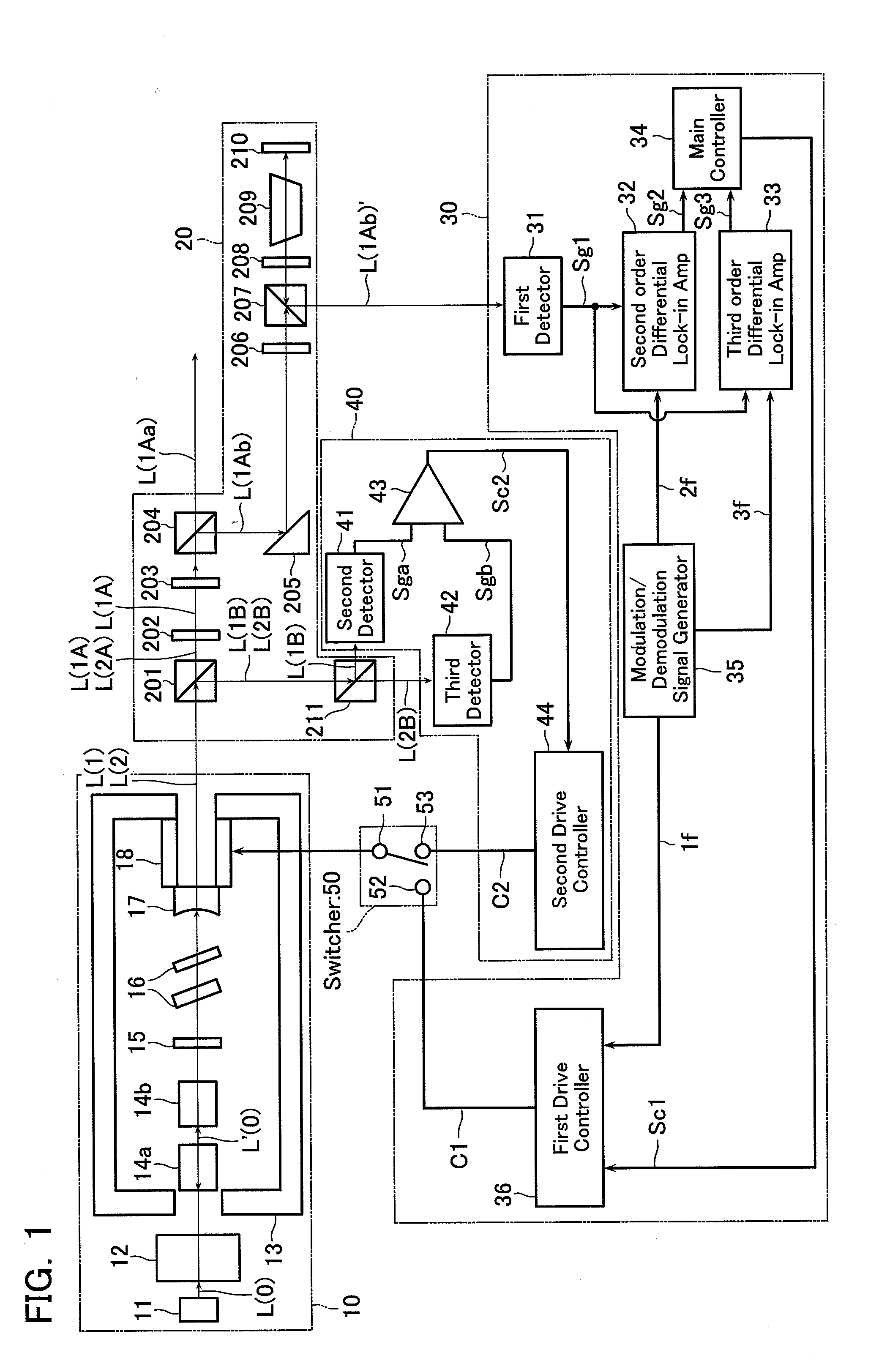
[0019]A configuration of the laser frequency stabilizing device according to the embodiment of the present invention is described. FIG. 1 is a brief block diagram of the laser frequency stabilizing device according to the embodiment of the present invention. As shown in FIG. 1, the laser frequency stabilizing device comprises a laser light producer 10, a laser light spectrometer 20, a first controller 30, a second controller 40, and a switcher 50. The laser light producer 10 has a function of producing a laser light. The laser light spectrometer 20 has a function of spectrally decomposing the laser light produced at the laser light producer 10. The first controller 30 and the second controller 40 have a function of detecting the laser light and controlli...


PUM


Abstract

A laser frequency stabilizing device comprises a laser light producer operative to produce and emit a laser light containing a first and a second longitudinal mode light having different wavelengths; a spectrometer operative to spectrally decompose the laser light into the first longitudinal mode light and the second longitudinal mode light; a first detector operative to detect the light output signal from a absorption cell; a second and third detector operative to detect the signal intensity of the first and second longitudinal mode light; an actuator operative to change the resonant cavity length; a first drive controller operative to detect the saturated absorption signal from the light output signal detected at the first detector and control driving the actuator based on the saturated absorption signal; a second drive controller operative to control driving the actuator such that the signal intensity of the first longitudinal mode light detected at the second detector and the signal intensity of the second longitudinal mode light detected at the third detector have a ratio of a certain value; and a switcher operative to switch the control of the detector between the control by the first drive controller and the control by the second drive controller.

Description

CROSS-REFERENCE TO RELATED APPLICATION[0001]This application is based upon and claims the benefit of priority from the prior Japanese Patent Application No. 2008-62737, filed on Mar. 12, 2008, the entire contents of which are incorporated herein by reference.BACKGROUND OF THE INVENTION[0002]1. Field of the Invention[0003]The present invention relates to a laser frequency stabilizing device, laser frequency stabilizing method and laser frequency stabilizing program for changing the resonant cavity length based on a light output signal to stabilize the oscillation frequency of a laser light.[0004]2. Description of the Related Art[0005]A continuous-wave oscillation, 532-nm range solid laser uses a Nd:YAG crystal or the like as a gain medium, which is pumped with a semiconductor laser. The wavelength of such the solid laser is utilized as the standard for lengths. An actual measurement using a wavelength of the laser light requires oscillations of the laser at a single frequency, that i...

Claims


Application Information

Patent Timeline
Patent Type & Authority Applications(United States)
IPC IPC(8): H01S3/13H01S3/08
CPCH01S3/08004H01S3/09415H01S3/109H01S3/137H01S3/1673H01S3/1396H01S3/1398H01S3/1611H01S3/1392
Inventor MASUDA, HIROKIMIYATA, KAORUSAKAI, HISAYOSHI
Owner MITUTOYO CORP
Why Eureka
Try Eureka