Low-speckle light source device

a laser light source and low-speckle technology, applied in the field of laser light source devices, can solve the problems of degrading the quality of acquired images, affecting the illumination performance of the illumination device employing the laser light source device, and the speckle reduction effect of the modulation applied to the mode coupling between multiple modes in the multimode optical fiber may not be visually recognizable, so as to achieve the speckle reduction level visually recognizable and reduce the coherence of laser ligh

Inactive Publication Date: 2009-09-17
FUJIFILM CORP
View PDF4 Cites 25 Cited by
  • Summary
  • Abstract
  • Description
  • Claims
  • Application Information

AI Technical Summary

Benefits of technology

[0008]In view of the above-described circumstances, the present invention is directed to providing a laser light source device which inexpensively achieves a visually recognizable level of speckle reduction by reducing the coherence of the laser light.

Problems solved by technology

However, an illumination device employing the laser light source device may suffer from degradation of illumination performance caused by an uneven illumination pattern (hereinafter referred to as “speckle”) due to coherence of the laser light.
Further, in an imaging apparatus employing the laser light source device as the illumination device, the speckle of the laser light may significantly degrade quality of an acquired image.
However, since the speckle phenomenon is caused by the coherence of the laser light, if reduction of the coherence of the laser light is insufficient in the laser light source devices disclosed in the above patent documents, the speckle reduction effect of the modulation applied to the mode coupling between multiple modes in the multimode optical fiber may not be visually recognizable.
Namely, it has been found that the speckle reduction effect of the laser light source devices disclosed in the above patent documents is not visually recognizable if the laser light guided through the multimode optical fiber has a large residual polarized component.
Further, it is difficult to produce the fiber bundle of fibers, which have fiber lengths that differ from each other by a length not less than the coherence length, in the laser light source device disclosed in the above-mentioned Japanese Unexamined Patent Publication No. 6(1994)-167640, and use of such a fiber bundle may lead to cost increase of the laser light source device.

Method used


Image

  • Low-speckle light source device
  • Low-speckle light source device
  • Low-speckle light source device

Examples


Embodiment Construction

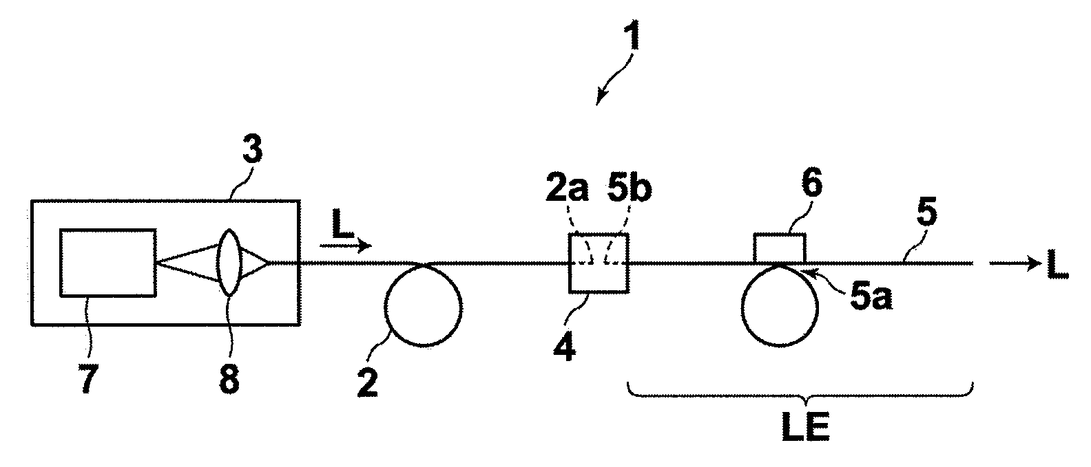
[0022]Hereinafter, a laser light source device of the present invention will be described with reference to the drawings. FIG. 1 illustrates the schematic configuration of a laser light source device 1 of the invention. As shown in FIG. 1, the laser light source device 1 includes: an optical fiber 2; a laser module 3 to emit laser light L to be outputted from the optical fiber 2; a multimode optical fiber 5 connected to the fiber 2 via an optical connector 4; and an actuator 6 to apply vibration to a looped portion 5a of the multimode optical fiber 5.

[0023]The laser module 3 includes: a light source unit 7 including a laser package (not shown); and a light collection optical system 8 to collect and direct the laser L emitted from the light source unit 7 into the optical fiber 2. In this embodiment, the laser light L has, as one example, a wavelength of 405 nm and a power of 100 mW, however, this is not intended to limit the invention.

[0024]In this embodiment, the optical fiber 2 is ...


PUM

PropertyMeasurementUnit
core diameteraaaaaaaaaa

Abstract

A laser light source device which can inexpensively achieve a visually recognizable level of speckle reduction is disclosed. The laser light source device includes: a laser module including a light source and a first optical waveguide, wherein light emitted from the light source is outputted from an output end of the first optical waveguide; a second optical waveguide connected to the first optical waveguide, wherein the light outputted from the output end of the first optical waveguide is inputted to an input end of the second optical waveguide and guided through the second optical waveguide; and an intensity modulation unit disposed in the vicinity of the second optical waveguide, the intensity modulation unit applying intensity modulation to the second optical waveguide, wherein a core diameter at the input end of the second optical waveguide is larger than a core diameter at the output end of the first optical waveguide.

Description

BACKGROUND OF THE INVENTION[0001]1. Field of the Invention[0002]The present invention relates to a laser light source device, and in particular to a laser light source device having reduced speckle of laser light emitted therefrom.[0003]2. Description of the Related Art[0004]Laser light source devices have conventionally been used as an illumination device for use with an endoscope or interferometer. Such an illumination device is required to provide uniform illumination light. However, an illumination device employing the laser light source device may suffer from degradation of illumination performance caused by an uneven illumination pattern (hereinafter referred to as “speckle”) due to coherence of the laser light. Further, in an imaging apparatus employing the laser light source device as the illumination device, the speckle of the laser light may significantly degrade quality of an acquired image.[0005]Japanese Unexamined Patent Publication No. 2003-156698 proposes a laser ligh...

Claims


Application Information

Patent Timeline
Patent Type & Authority Applications(United States)
IPC IPC(8): G02F1/01
CPCG02B6/262H01S3/005G02B27/48G02B6/3502
Inventor SHIMOTSU, SHINICHI
Owner FUJIFILM CORP
Why Eureka
Try Eureka