
Electrowetting retroreflector devices, systems, and methods

a retroreflector and electro-electromagnetic technology, applied in the field of retroreflector devices, systems and methods, can solve the problems of difficult scaling to the array size needed, prior approaches such as multiple-quantum wells, and are typically limited to very narrow-spectrum infra-red

Active Publication Date: 2009-09-17
UNIVERSITY OF CINCINNATI
View PDF10 Cites 34 Cited by
  • Summary
  • Abstract
  • Description
  • Claims
  • Application Information

AI Technical Summary

Benefits of technology

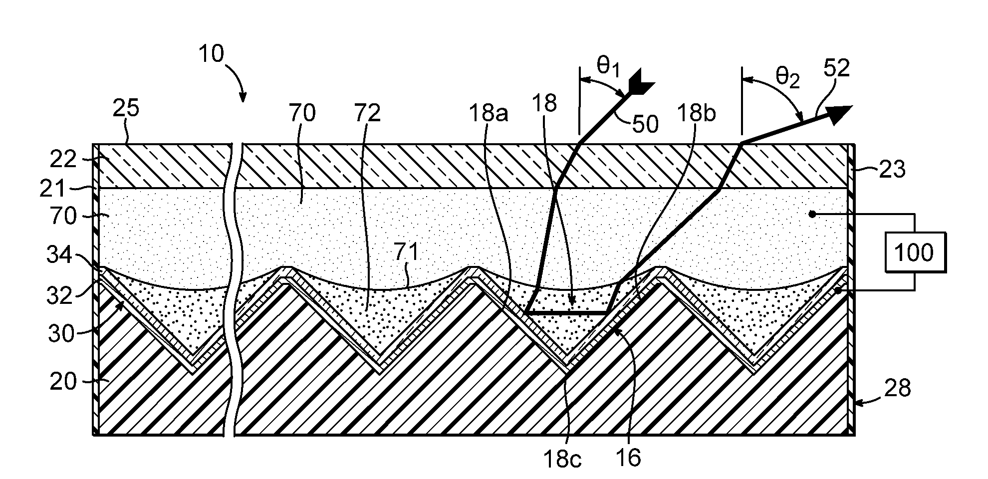
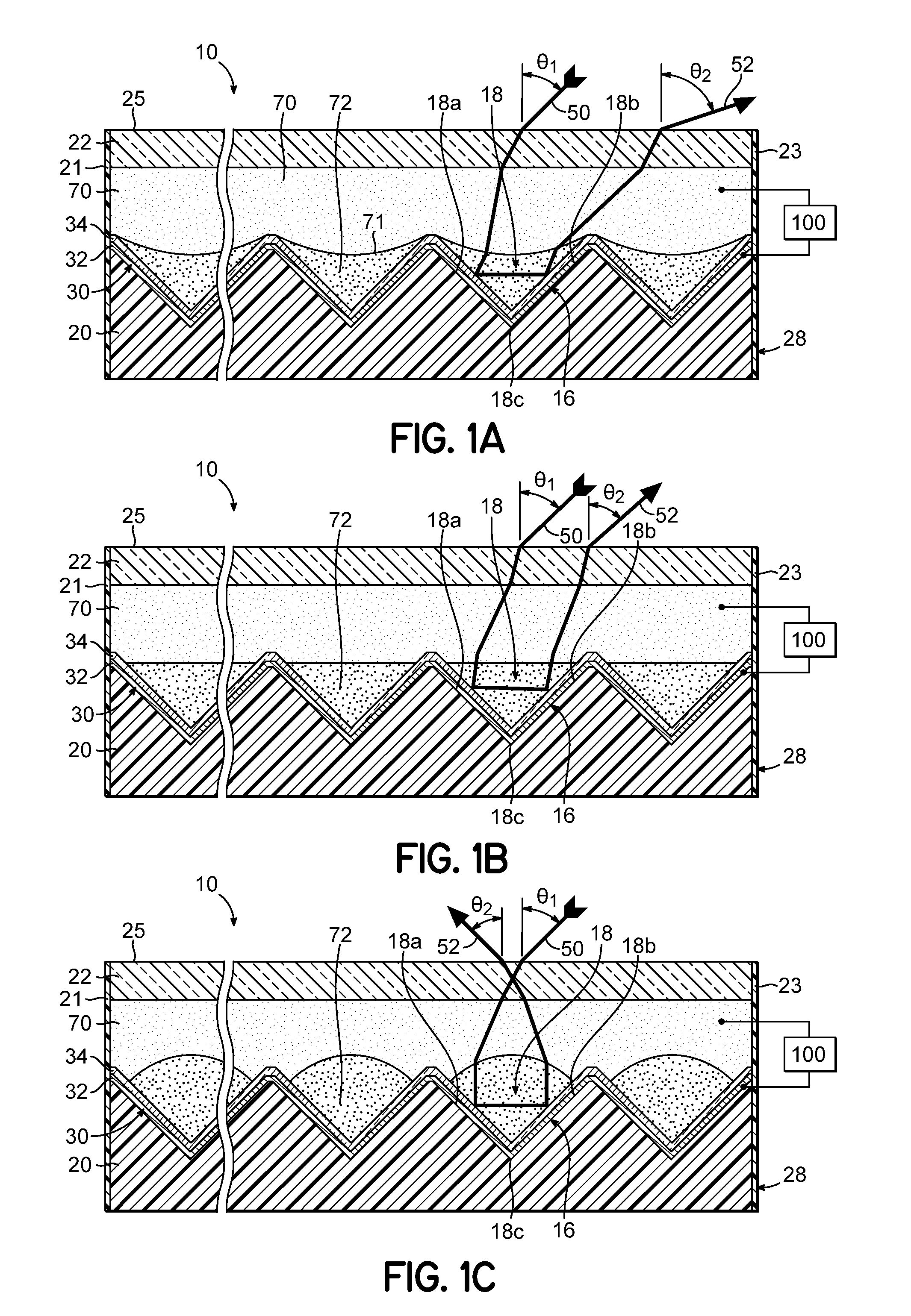
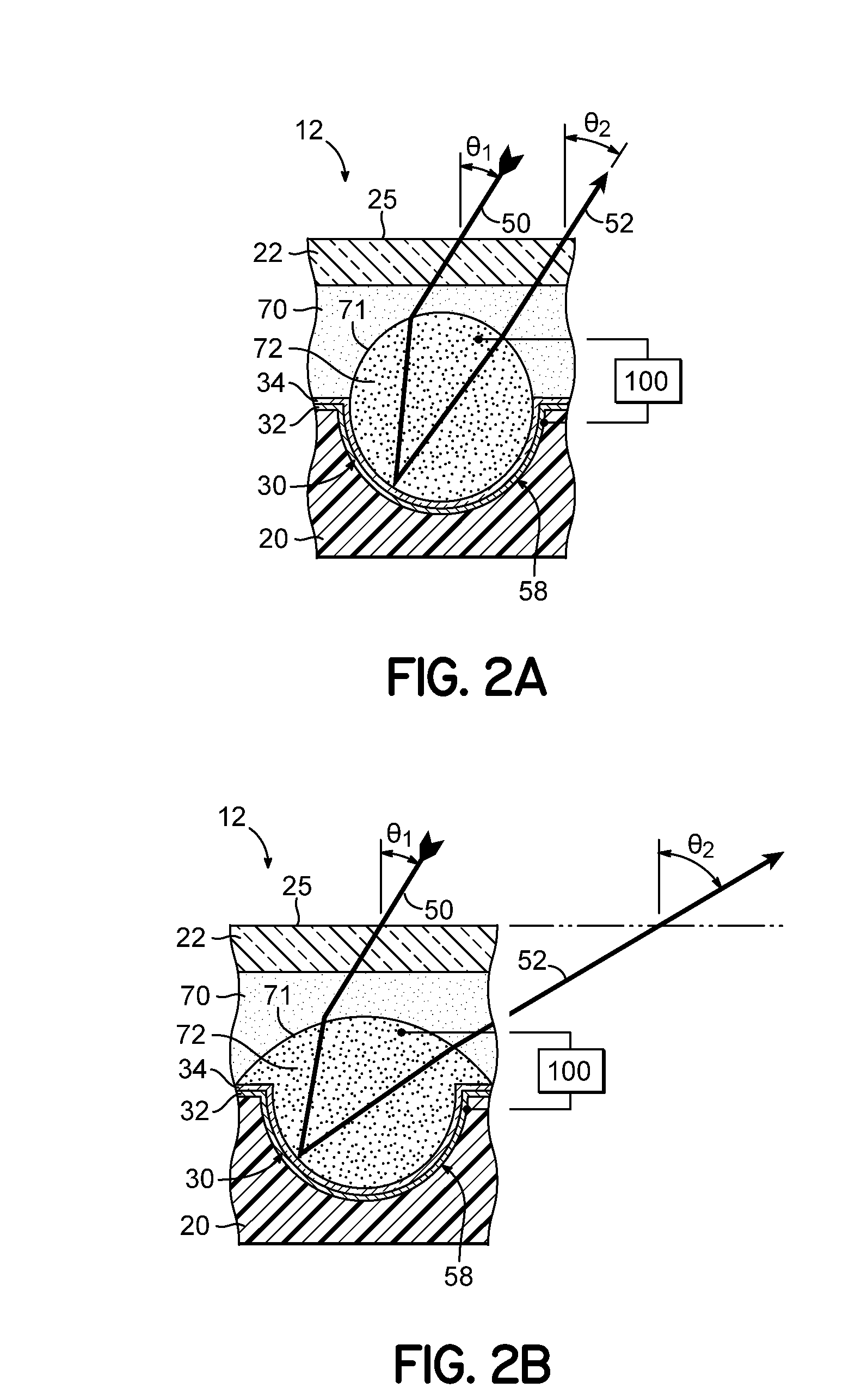
[0010]In another embodiment, a method is provided for regulating retroreflection from a retroreflective surface in response to an input signal. The method includes directing incident light through polar and non-polar fluids toward the retroreflective surface with an incident angle, retroreflecting the incident light from the retroreflective surface as reflective light, directing the refle...

Problems solved by technology

However, all conventional approaches, such as micro-electromechanics, are difficult to scale to the arrays sizes needed for visualization at a distance; and prior approaches, such as multiple-quantum wells, are typically limited to very narrow-spectrum infra-red.

Method used


Image

  • Electrowetting retroreflector devices, systems, and methods
  • Electrowetting retroreflector devices, systems, and methods
  • Electrowetting retroreflector devices, systems, and methods

Examples


example 1

[0051]Arrayed corner-cubes of approximately 800 μm individual size were micro-replicated in two-part chemically cured epoxy using a vacuum-oven assist for air-bubble removal and curing. Approximately 300 nm of Al was then thermally evaporated onto the substrate. The thicker Al film provided higher reflectivity for this work, but with an optical-quality metal evaporator such large thickness would be unnecessary. Next, 1 μm of Parylene C was vapor deposited, which would be later shown to require greater than 10V for proper electrowetting operation. Alternately, to allow approximately 3V operation, one can deposit approximately 100 nm of Al2O3 via sputtering or atomic-layer-deposition. A hydrophobic surface was next obtained by dip-coating the sample in Cytonix Fluoropel 1601V and thermally curing the fluoropolymer to a thickness of approximately 200 nm. Next, the sample was reverse-dip-coated into a dodecane oil film floating on de-ionized water. This self-assembled the oil into each ...


PUM


Abstract

Switchable retroreflector devices that are modulated via electrowetting. The devices include an electrically-conductive polar fluid and a non-polar fluid that is immiscible with the polar fluid. The polar and the non-polar fluids differ in at least one optical property. The fluids are contained in a fluid vessel, or an array of fluid vessels. The fluids are at least partially viewable. A voltage source is configured to selectively apply an electromechanical force to the polar fluid causing repositioning and / or geometrical change of the fluids such that retroreflection in created, or suppressed, by optical refraction or by optical attenuation.

Description

CROSS REFERENCE TO RELATED APPLICATIONS[0001]This application claims the benefit of U.S. Provisional Application No. 61 / 037,123, filed Mar. 17, 2008. The disclosure of this provisional application is hereby incorporated by reference herein in its entirety.BACKGROUND[0002]The invention relates generally to retroreflector devices, systems and methods.[0003]Electrowetting has been a highly attractive modulation scheme for a variety of optical applications. For example, electrowetting has been used to provide optical switches for fiber optics, optical shutters or filters for cameras and guidance systems, optical pickup devices, optical waveguide materials, and video display pixels.[0004]Retroreflectors are well known by those skilled in the art of conspicuity markings. Retroreflectors are most often comprised of glass beads or a truncated corner of a cube, with the latter exhibiting several-fold higher retroreflective efficiency. The term ‘retroreflection’ is refers to the scenario in w...

Claims


Application Information

Patent Timeline
IPC IPC(8): H04B10/00G02B26/00G02F1/29G02F1/17
CPCG02B5/124G02B26/005G02B5/128
Inventor HEIKENFELD, JASONKILARU, MURALISCHULTZ, PHILLIPO'NEILL, DANIEL J.
Owner UNIVERSITY OF CINCINNATI
Learn More