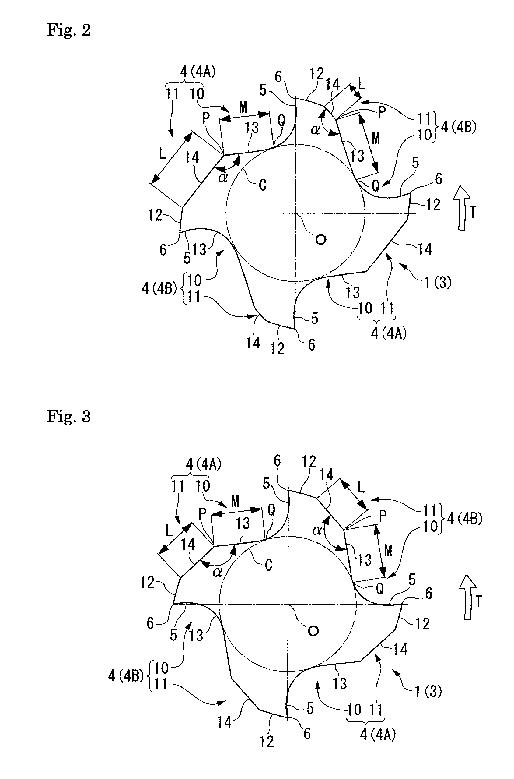
[0016]Since a large cross-sectional area can be secured as entirely the chip discharge flute in this end mill; even if a cutting edge, with a longer interval to the next cutting edge toward the end mill rotating direction side, generates a large amount of chips; the chip discharge flute can be prevented from becoming clogged. Further, since the cross-section shows that the flute bottom face forms a linear shape that goes from the tangent point, at which the flute bottom face touches the web thickness circle, toward the end mill rotating direction. The chips flow from the rake face, flow through the flute bottom face in the main flute portion which forms the concavely curved shape in the cross-section, flow along the above linear shape portion in the cross-section, and then are discharged toward the end mill rotating direction side. Therefore, a good performance for discharging the chips smoothly is available, even if the generated chips are bulky.
[0017]On the other hand, the flute bottom face in the sub-flute portion, which intersects with the flute bottom face in the main flute portion, also forms a linear shape in a cross-section. Comparing this linear shape with the convexly curved shapes in a cross-section formed as the corresponding portions of the aforementioned conventional end mills, as a larger cross-sectional area of the flute than others can be secured, this linear shape more reliably prevents an occurrence of chip clogging. Additionally, since the intersection angle between these flute bottom faces can increase, even if the chips pass beyond the intersecting ridgeline portion and flow into the sub-flute portion, the end mill is free from an occurrence of chip catching. On the other hand, in conventional end mills having a center concaved round shape as their flute bottom
face shape and / or as their secondary flank
face shape, this chip catching tends to occur. Also, the intersecting ridgeline portion can be free from damages by having a secured strength. Moreover, the back
metal of the cutting edge located toward the end mill rotating direction side in the sub-flute portion can be made larger than those of the conventional end mills, and thus sufficient rigidity and strength of the cutting edge can be secured. Therefore, the aforementioned cutting edges with a longer interval to the next cutting edge toward the end mill rotating direction side can be free from damages, even if the cutting edges have an increased cutting load.
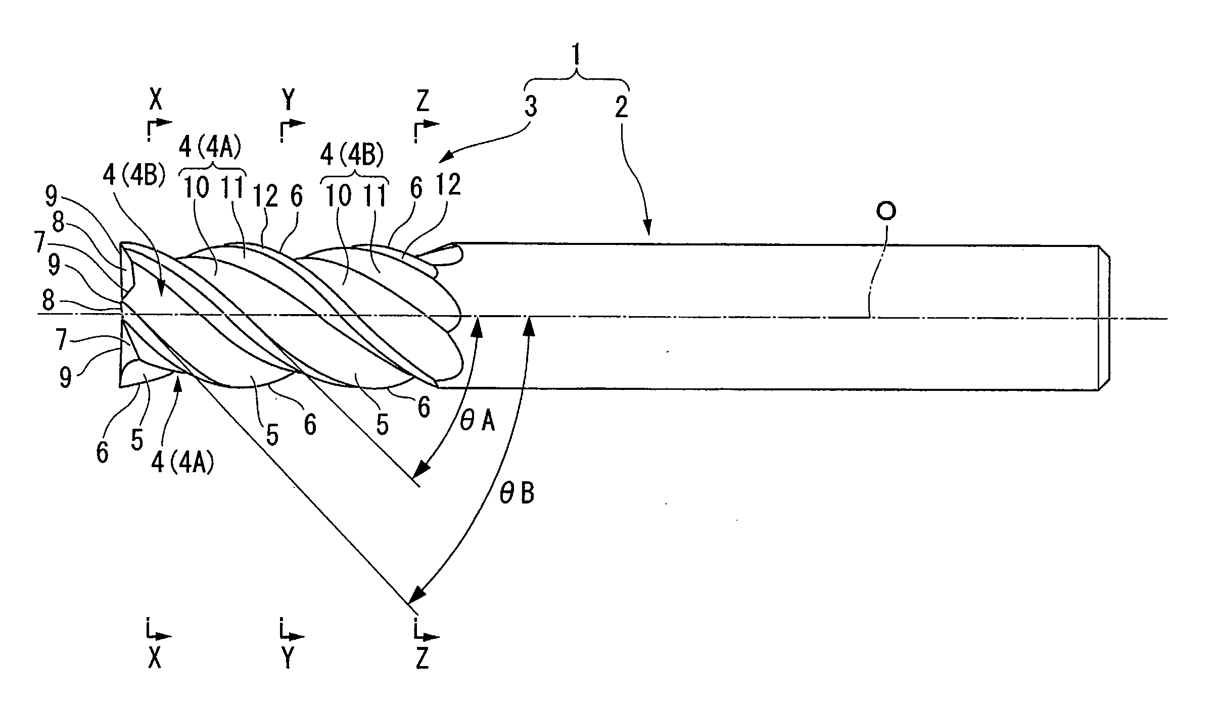
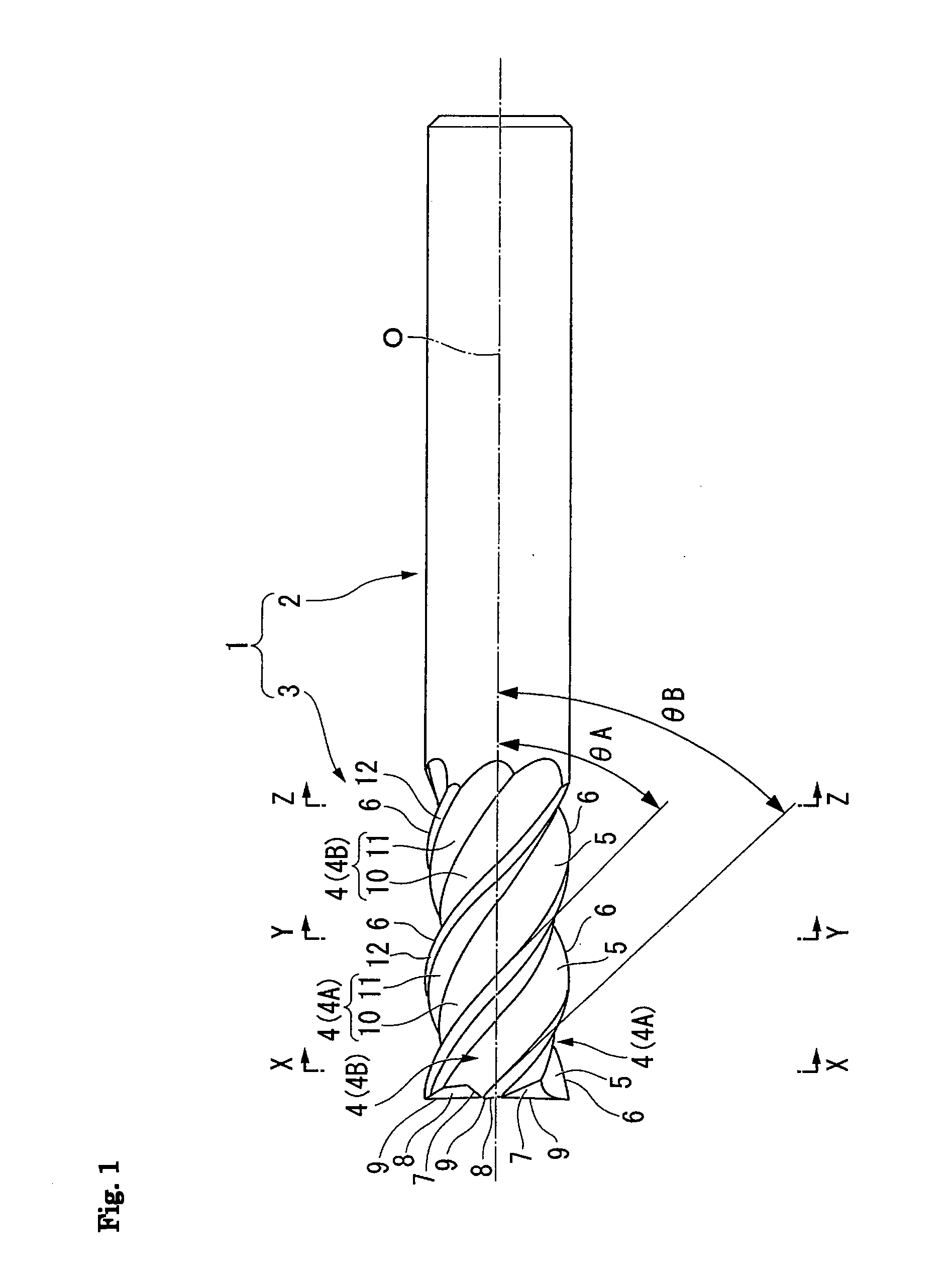
[0018]Additionally, a variable lead end mill; in which the
helix angle[s] of the cutting edge[s] using wall[s] of the chip discharge flute[s], of which is [are] at least one or more, facing toward the end mill rotating direction as rake face[s] is [are] different from those of the others; has features that any cross-section perpendicular to the axis of the end mill body, shows that each chip discharge flute with various
helix angles, has variable flute widths. Also a cross-section perpendicular to the axis of the end mill body shows that a chip discharge flute, with a wider flute width than that of other chip discharge flutes, has a longer linear portion on the flute bottom face in the sub-flute portion than that of other chip discharge flutes. Therefore, a wider flute, namely, the chip discharge flute, in which a cutting edge with a longer interval to the next cutting edge toward the end mill rotating direction side, can secure a larger cross-sectional area of the flute, and thus the chip discharge flute can be more reliably prevented from becoming clogged.
[0019]Moreover, a chip discharge flute, in which the
helix angle of the cutting edge in the chip discharge flute is different from a
helix angle of a cutting edge in a next chip discharge flute toward the end mill rotating direction side, has a flute in which its flute width is gradually variable across the length of the axis direction. I.e., this chip discharge flute has a form in which, in a cross-section perpendicular to the axis, the linear shape portion on the flute bottom face in the sub-flute portion becomes gradually longer toward a direction of the wider flute width along the axis. Therefore, a flute portion in which a flute width of each chip discharge flute is wider, namely, a flute portion in which a large cross-sectional area of the flute is secured to flow a large amount of chips generated by the cutting edge with a longer interval to the next cutting edge toward the end mill rotating direction side, and thus an occurrence of chip clogging is effectively prevented.
[0020]The variable end mill of the present invention mentioned-above is with the chip discharge flute in which a large amount of bulky chips, which are generated by the cutting edge with a longer interval to the next cutting edge toward the end mill rotating direction side, flows in there a large cross-sectional area thereof can be secured the chips can flow there smoothly; and thus an occurrence of chip clogging can be prevented.
[0021]Therefore, in the chip discharge flute, an intersecting ridgeline portion between the main flute portion and the sub-flute portion becomes free from damages; and then the cutting edge toward the end mill rotating direction side becomes free from damages, too. Also, a smooth cutting operation with no chattering vibration is reliably available for an extended period of time.

