Assembly for driving gas turbine accessories

a technology for accessories and gas turbines, applied in the direction of gearing details, efficient propulsion technologies, machines/engines, etc., can solve the problems of excessive size and weight of accessory drive gearboxes, and achieve the effect of reducing the overall weight of the assembly

a technology for accessories and gas turbines, applied in the direction of gearing details, efficient propulsion technologies, machines/engines, etc., can solve the problems of excessive size and weight of accessory drive gearboxes, and achieve the effect of reducing the overall weight of the assembly

US20090232640A1Active Publication Date: 2009-09-17SAFRAN TRANSMISSION SYST

Image

  • Assembly for driving gas turbine accessories
  • Assembly for driving gas turbine accessories
  • Assembly for driving gas turbine accessories

Examples


Embodiment Construction

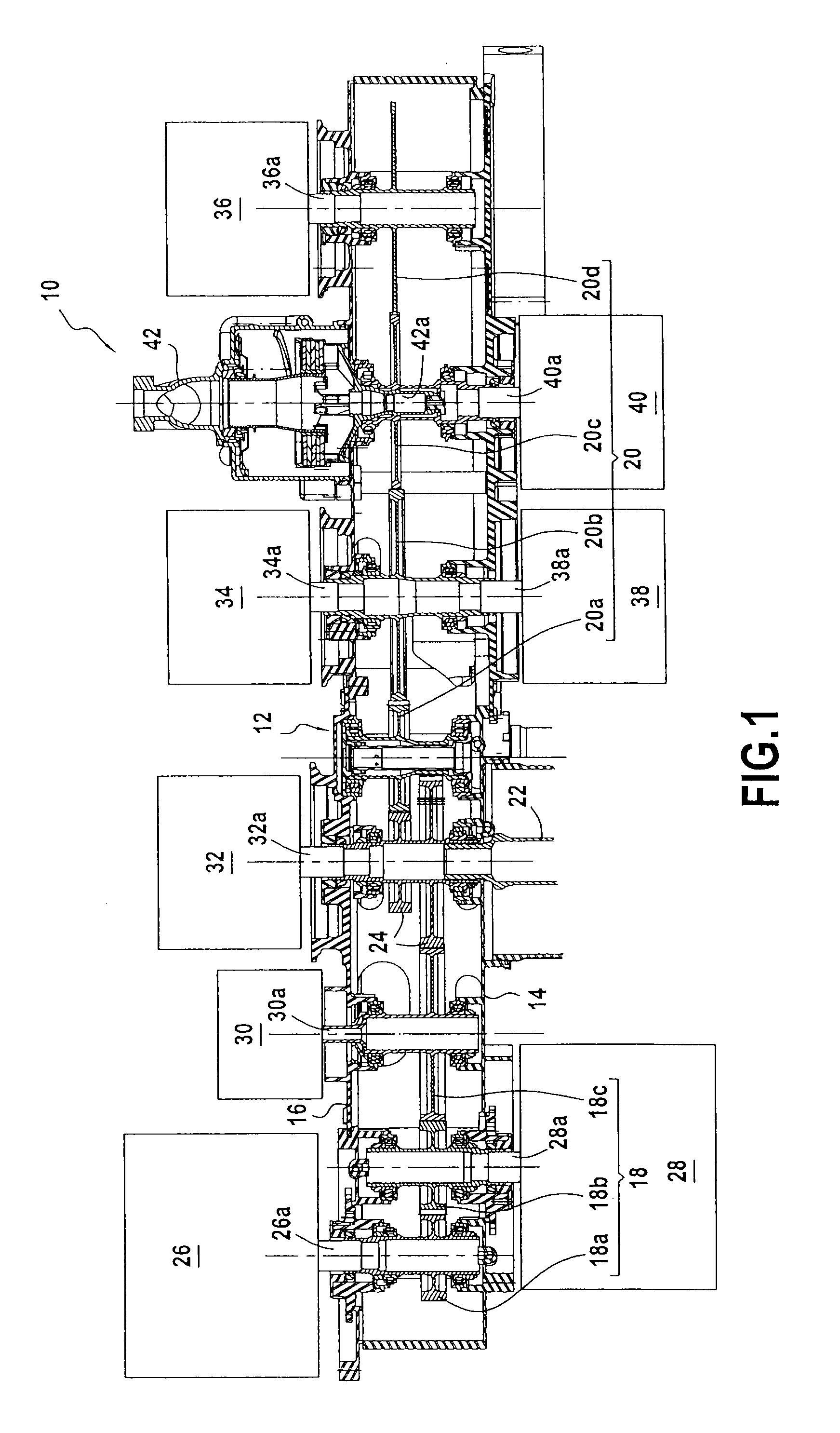
[0025]FIG. 1 is a longitudinal section of an assembly 10 for driving accessories of an airplane gas turbine. Naturally, the invention also applies to helicopter engine gas turbines, and also to auxiliary power units.

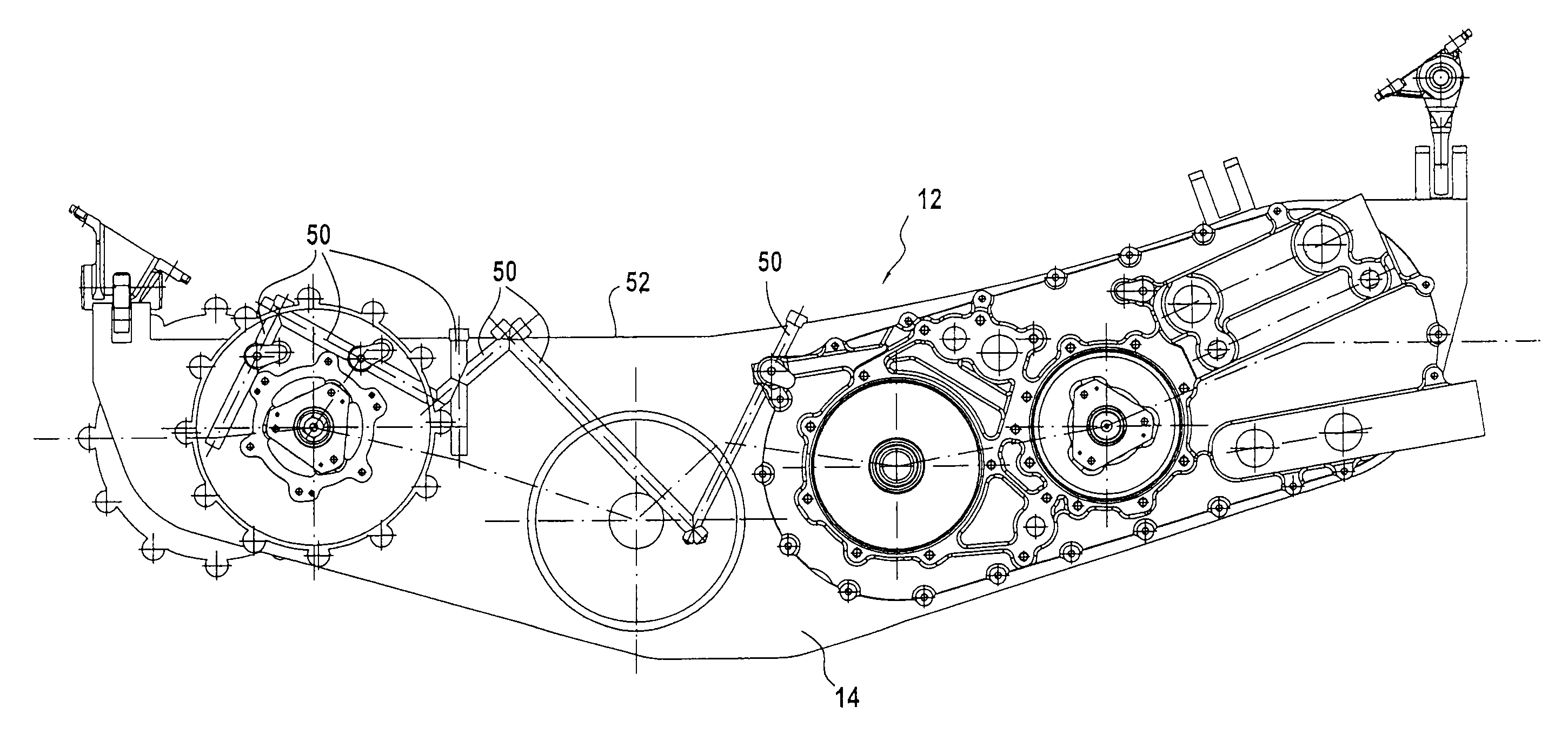
[0026]The assembly 10 comprises in particular a substantially rectangular gearbox 12 having a front side face 14 and a rear side face 16 opposite the front face.

[0027]The gearbox 12 houses two gear trains that extend in a longitudinal direction, namely: a first gear train 18 made up of three toothed wheels 18a to 18c that mesh with one another, and a second gear train 20, different from the first, made up of four toothed wheels 20a to 20d that mesh with one another.

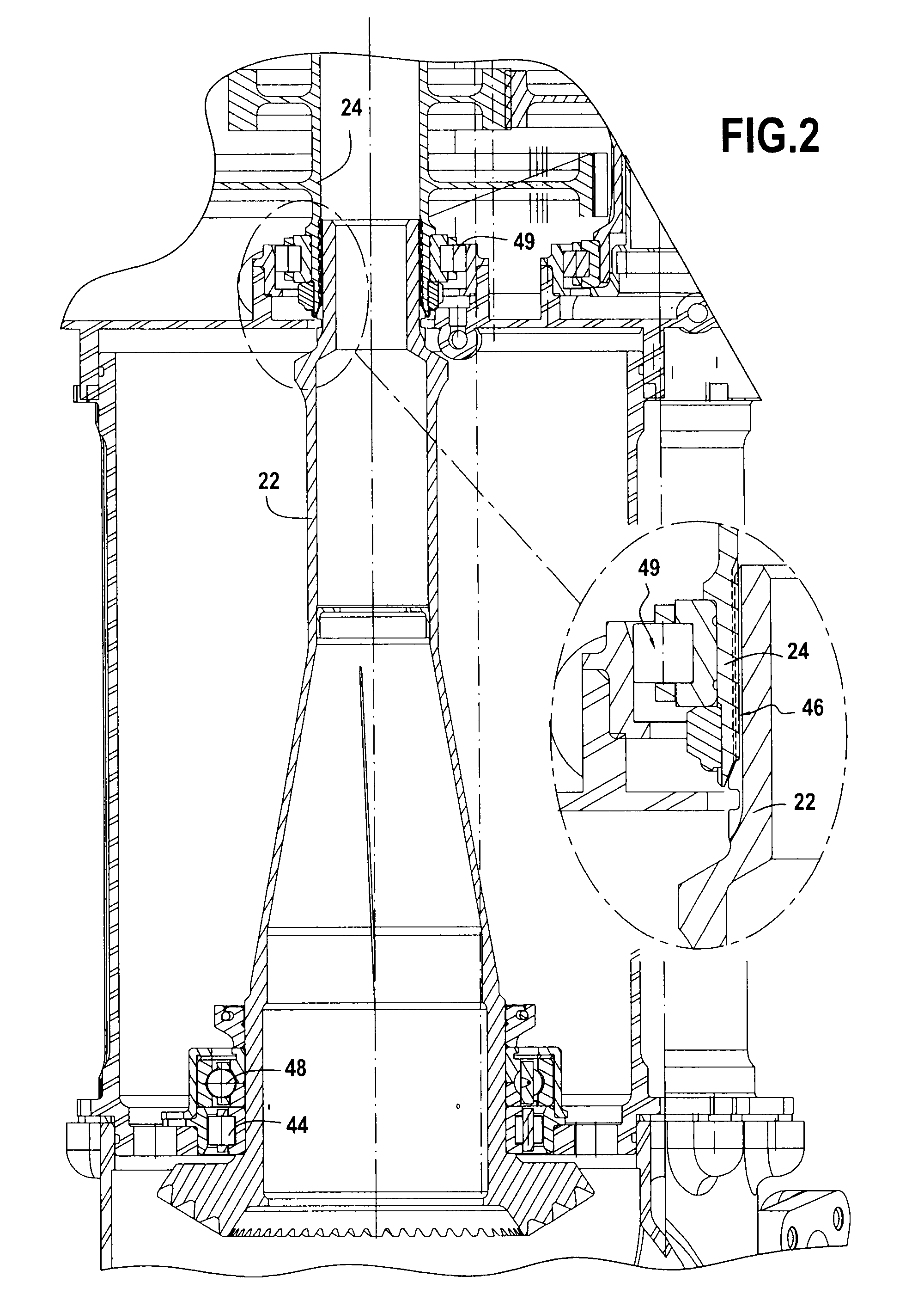
[0028]A power transmission shaft 22 (shown in part in FIG. 1) takes mechanical power from a shaft of the turbine (not shown in the figures), and transmits it to the two gear trains 18 and 20. For this purpose, the power transmission shaft 22 is coupled to rotate with both gear trains by means of a pair of toot...


PUM


Abstract

The invention provides an assembly for driving accessories of a gas turbine, the assembly comprising: a gearbox having a front side face and a rear side face opposite the front face and having mounted therein a first gear train made up of three toothed wheels meshing with one another, and a second gear train made up of four toothed wheels meshing with one another; a power transmission shaft that is coupled in rotation with the first and second gear trains by means of a toothed wheel pair, and that emerges from the front side face of the gearbox; and nine distinct gas turbine accessories mounted against the side faces of the gearbox, and each including a respective drive shaft that is coupled in rotation with one of the toothed wheels of the two gear trains.

Description

BACKGROUND OF THE INVENTION[0001]The present invention relates to the general field of gas turbines and it relates more particularly to the configuration of a gearbox for driving accessories of a gas turbine.[0002]The field of application of the invention is that of gas turbines for airplane or helicopter engines, and also for auxiliary power units (APUs).[0003]The gas turbine engines of airplanes or helicopters generally include a gearbox for driving a plurality of turbine accessories or pieces of auxiliary equipment, such as in particular various pumps for producing hydraulic energy, for feeding fuel, for lubrication, electricity generators for producing electrical power, etc. Such a gearbox is commonly referred to as an accessory gearbox (AGB).[0004]In known manner, a gearbox for driving accessories comprises one of more gear trains, each made up of a plurality of toothed wheels that are driven in rotation by a power transmission shaft, which shaft is coupled to a shaft of the tu...

Claims


Application Information

Patent Timeline
17 Sep 2009
Publication
US20090232640A1
IPC
F01D15/12; F16C19/54; F16H57/02; F02C6/00
CPC
Y02T50/671; F02C7/36; F05D2220/50; F02C7/32; Y10T74/2186; Y02T50/60
Inventors
DEPERROIS, ANDRE RAYMOND CHRISTIAN; GRAND, YVON