
Evaporating method for forming thin film

a technology of evaporation method and thin film, which is applied in the direction of vacuum evaporation coating, electroluminescent light source, coating, etc., can solve the problems of time-consuming process of forming multiple layers and corrupted evaporating source material for forming films, and achieve efficient stacking and good quality

Active Publication Date: 2009-09-17
SAMSUNG DISPLAY CO LTD
View PDF7 Cites 113 Cited by
  • Summary
  • Abstract
  • Description
  • Claims
  • Application Information

AI Technical Summary

Benefits of technology

[0024]According to aspects of the present invention, a multi-layer organic film in which various material layers are stacked can be formed in single evaporation process. Thus, there is no time loss between operations of stacking the organic films, so that layers can be efficiently stacked.
[0025]According to aspects of the present invention, since layers within a multi-layer organic film are formed successively, it is possible to obtain organic films with good quality without ventilating a chamber between operations of stacking layers in an organic film.
[0026]Also, aspects of the present invention are advantageous for forming large-sized substrates.

Problems solved by technology

Therefore, a process of forming multiple layers may be time-consuming.
However, in this described method, deposition from one evaporation source is performed only after completing deposition from another evaporation source within one chamber.
Thus, the evaporating source material for forming a film may be corrupted in the second evaporating operation due to the residue gases from the first evaporating operation.

Method used


Image

  • Evaporating method for forming thin film
  • Evaporating method for forming thin film
  • Evaporating method for forming thin film

Examples


Embodiment Construction

[0039]Reference will now be made in detail to the present embodiments of the present invention, examples of which are illustrated in the accompanying drawings, wherein like reference numerals refer to the like elements throughout. The embodiments are described below in order to explain the present invention by referring to the figures.

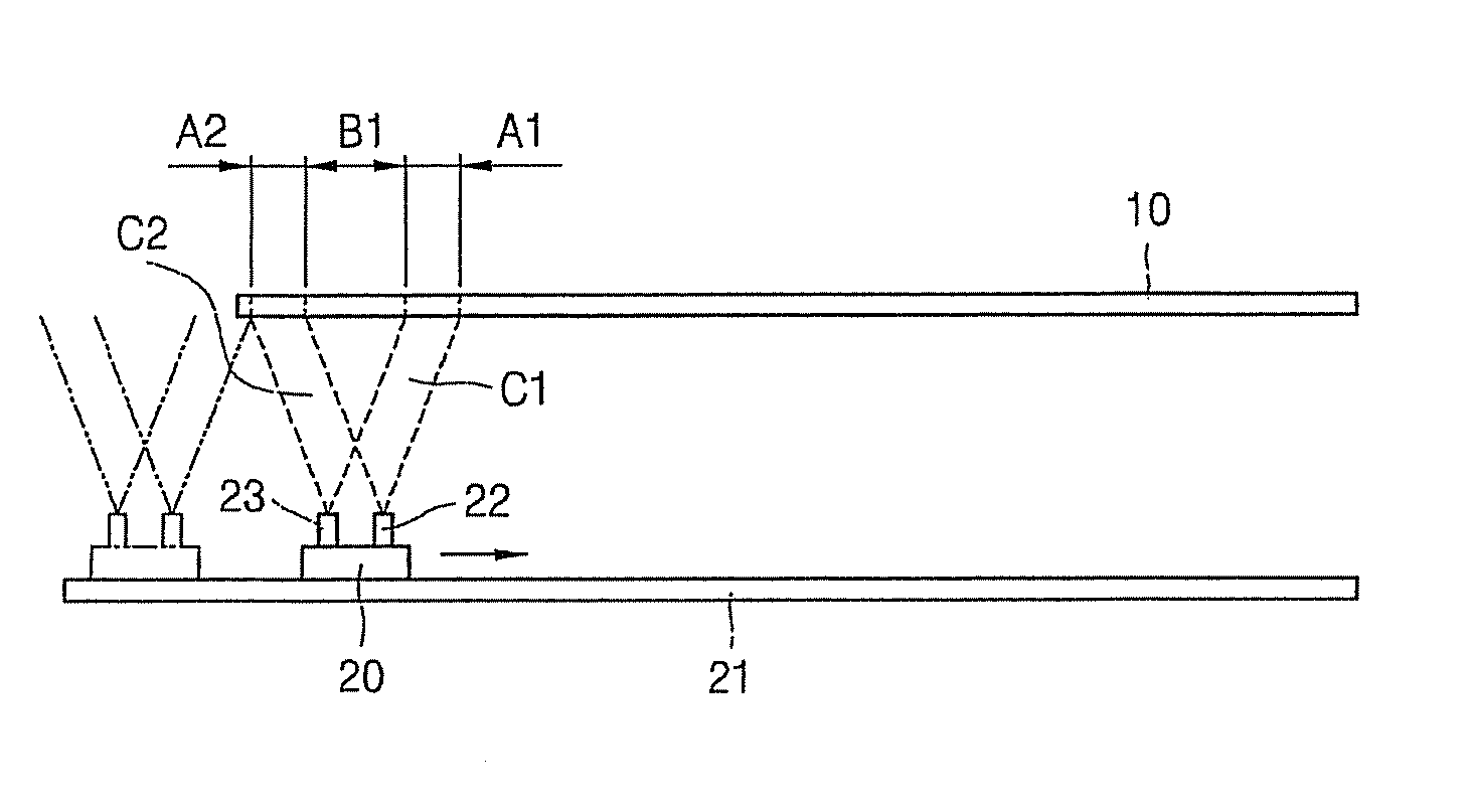
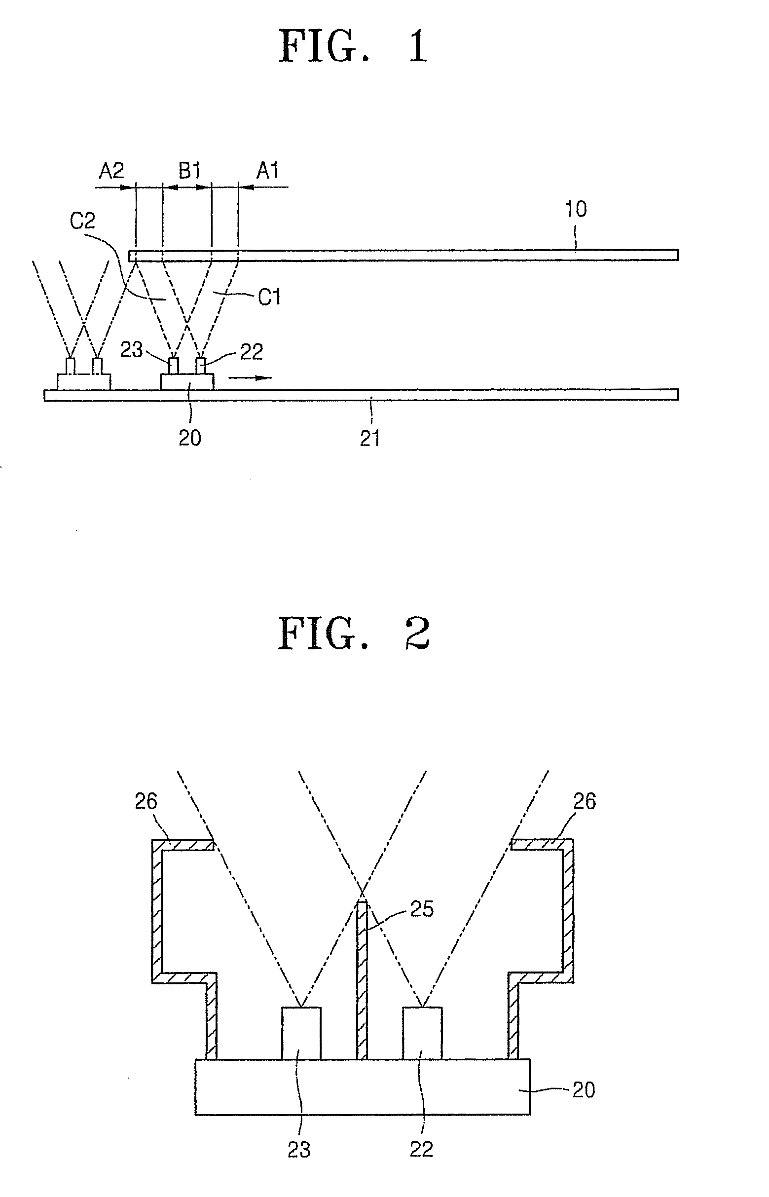
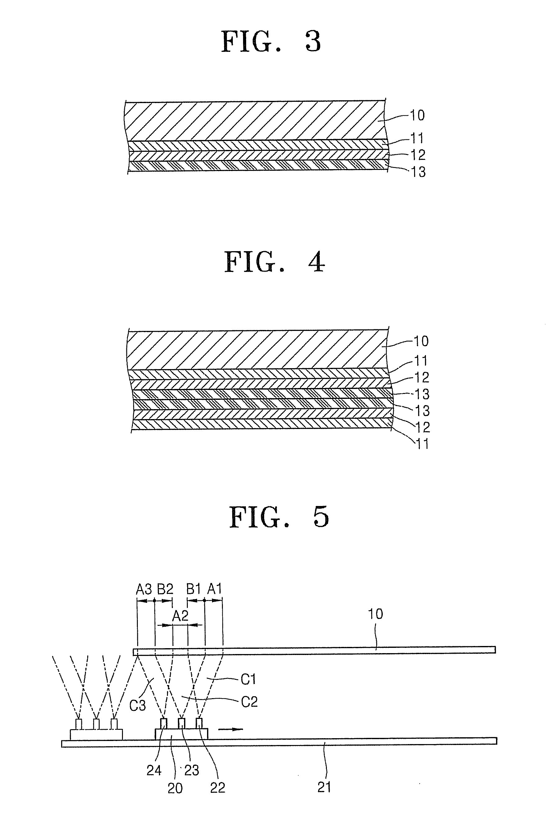
[0040]FIG. 1 is a sectional view schematically showing an evaporation system performing a method of forming a thin-film, according to an embodiment of the present invention.

[0041]Although a chamber is not shown in FIG. 1 for convenience of explanation, all components shown in FIG. 1 may be disposed in a chamber maintained at an appropriate vacuum level. Alternatively, the chamber may be maintained in an inert atmosphere including inert gases.

[0042]A substrate 10, which is an object to be processed, is disposed within the chamber. The substrate 10 may be a substrate for a flat-panel display device, and more generally, any substrate having a large surfac...


PUM

PropertyMeasurementUnit
sizeaaaaaaaaaa
speedaaaaaaaaaa
timeaaaaaaaaaa

Abstract

A method of forming a plurality of multi-layer organic films in a single process includes preparing a first evaporating source that evaporates a first evaporating source material onto a first deposition region and a second evaporating source that evaporates a second evaporating source material onto a second deposition region, wherein the first evaporating source material and the second evaporating source material are different from each other, adjusting the first evaporating source and the second evaporating source in order to obtain a first overlapping region in which the first deposition region and the second deposition region overlap each other, driving the first evaporating source and the second evaporating source to deposit the first evaporating source material and the second evaporating source material onto a portion of an object to be processed, and moving the first evaporating source and the second evaporating source from a first end of the object to a second end of the object to form a multilayer film comprising a first layer that is a deposition of only the first evaporating source material, a second layer that is a deposition of a mixture of the first evaporating source material and the second evaporating source material and a third layer that is a deposition of only the second source material.

Description

CROSS-REFERENCE TO RELATED APPLICATION[0001]This application claims the benefit of Korean Patent Application No. 2008-22592, filed Mar. 11, 2008, in the Korean Intellectual Property Office, the disclosure of which is incorporated herein by reference.BACKGROUND OF THE INVENTION[0002]1. Field of the Invention[0003]Aspects of the present invention relate to a method of forming a thin film, and more particularly, to an evaporating method for forming a thin film, wherein various types of multi-layer films can be formed on an object to be processed.[0004]2. Description of the Related Art[0005]An organic thin film including an emission material layer in a flat-panel display device, such as an organic light emitting display (OLED) device, is typically formed using a thin-film evaporation process in which a material to form the organic thin film is evaporated in vacuum conditions.[0006]Typically, only a single thin-film is obtained by performing the thin-film evaporation process once. Theref...

Claims


Application Information

Patent Timeline
Patent Type & Authority Applications(United States)
IPC IPC(8): C23C16/44
CPCC23C14/12H05B33/10C23C14/243C23C14/24H10K71/00H10K2101/80H10K2101/90
Inventor YOON, JI-HWANLEE, KWAN-HEEKWAK, JAE-HYUNKIM, DONG-HUNCHUN, MIN-SEUNGSON, JUNG-HA
Owner SAMSUNG DISPLAY CO LTD
Learn More