
Heated valve manifold for ampoule

a technology of valve manifold and ampoule, which is applied in the direction of chemical vapor deposition coating, coating, metal material coating process, etc., can solve the problems of cvd process or ald process type and composition, and the vapor deposition process using solid precursors may suffer several problems

Inactive Publication Date: 2009-09-17
APPLIED MATERIALS INC
View PDF12 Cites 45 Cited by
  • Summary
  • Abstract
  • Description
  • Claims
  • Application Information

AI Technical Summary

Benefits of technology

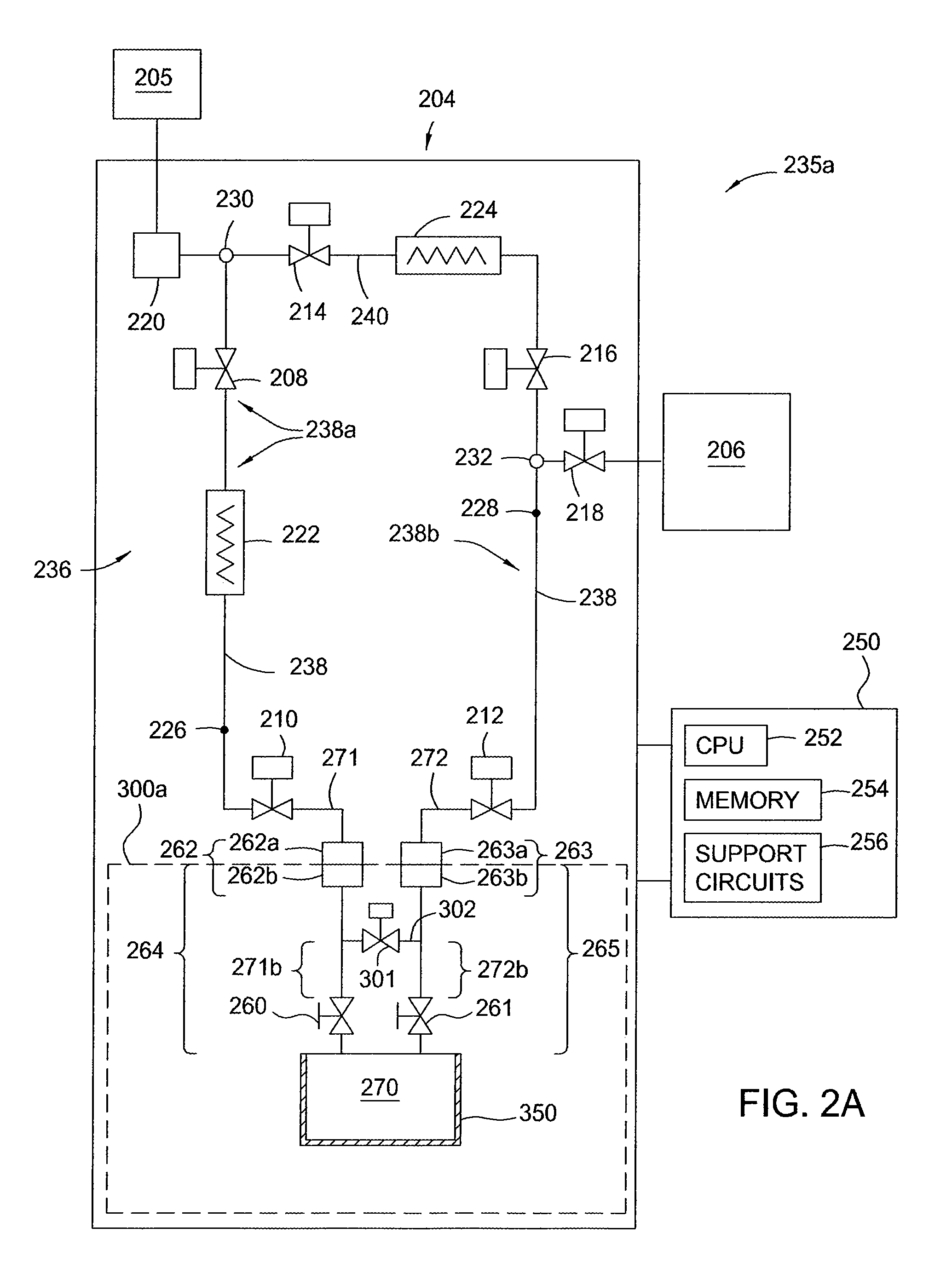
[0069]As noted above, in some aspects of the invention, some or all components of a precursor ampoule are charged with an inert gas, such as helium. The advantages of this are twofold. First, charging the ampoule body with a pressurized atmosphere of an inert gas chemically protects the precursor contained therein, even if some leakage occurs through any of the seals or valves in the ampoule assembly. This is particularly true for a solid precursor-containing ampoule assembly. Second, during a leak-checking procedure, such as that described above in conjunction with FIG. 2, a helium charge in the inlet line allows for leak-checking after new ampoule installation of not only of leakage into disconnect fittings 262, 263 from outside fluid delivery system 202 (see FIG. 2), but also of leakage through the outermost shut-off valve located in inlet line 264 and outlet line 265, such as manual valves 260, 261. The typical leak rate through shut-off valves, such as manual valves 260, 261, may be much higher than the typical leak rate externally, i.e., through the external seals of the valves, hence, checking for leakage through manual valves 260, 261 is an important procedure. In instances wherein it is undesirable for the ampoule body to be charged with an inert gas, which may be the case for certain liquid precursors, only a segment of the inlet and outlet lines may be charged with the inert gas. For example, referring to FIG. 2B, the segment of inlet line 264 disposed between manual valve 260 and valve 267, and the segment of outlet line 265 disposed between manual valve 261 and valve 268, may be the only regions of ampoule assembly 300a charged with an inert gas.

Problems solved by technology

Integrated circuits have evolved into complex devices that include millions of transistors, capacitors, and resistors on a single chip.
The type and composition of the layers that may be formed using a CVD process or an ALD process are limited by the ability to deliver a chemical reactant or precursor to the substrate surface.
A vapor deposition process that utilizes a solid precursor may suffer several problems.
While a solid precursor should be provided enough heated to be sublimed into a gaseous state, the solid precursor may decompose if exposed to too much heat.
Metal-organic solid precursors, which are usually very expensive, are especially susceptible to thermal decomposition and generally need to be maintained within narrow temperature and pressure ranges during a sublimation process.
Once decomposed, solid precursors may contaminate the remaining precursor in the vessel, the delivery system of conduits and valves, the processing chamber, as well as the substrate.
Furthermore, overheating a solid precursor may provide too high of a precursor concentration within the process gas, which may lead to wasted precursor that is never used or condensation of the precursor within the delivery lines or on the substrate.
These undesired solid or liquid particulates may become a source of contamination for the delivery system, processing chamber, or substrate.
However, the mixture of the liquid carrier material and the solid precursor may only be conducive within limited temperature and pressure ranges since the liquid carrier material may be evaporated and become a contaminant within the delivery system, processing chamber, or on the substrate.

Method used


Image

  • Heated valve manifold for ampoule
  • Heated valve manifold for ampoule
  • Heated valve manifold for ampoule

Examples


Embodiment Construction

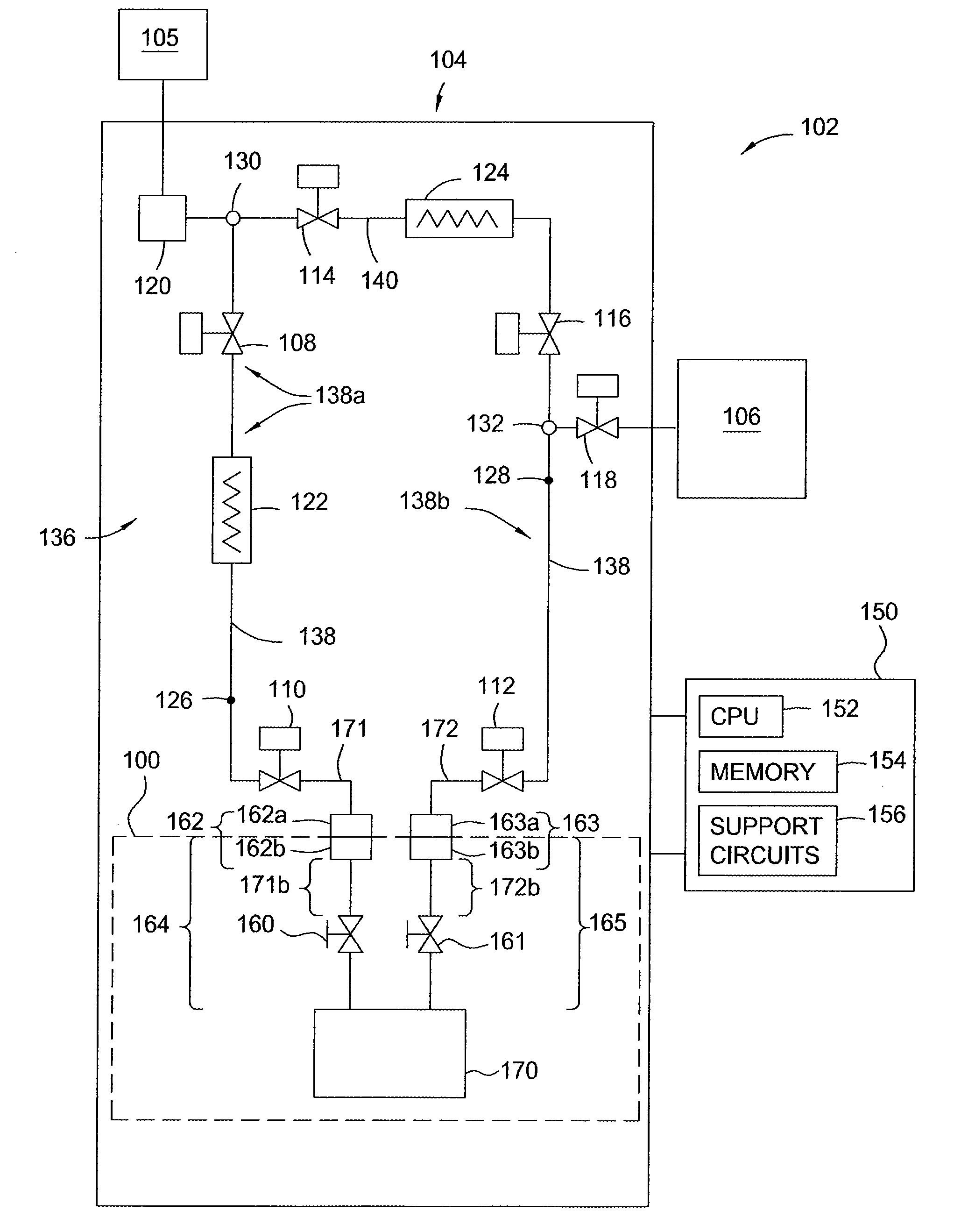
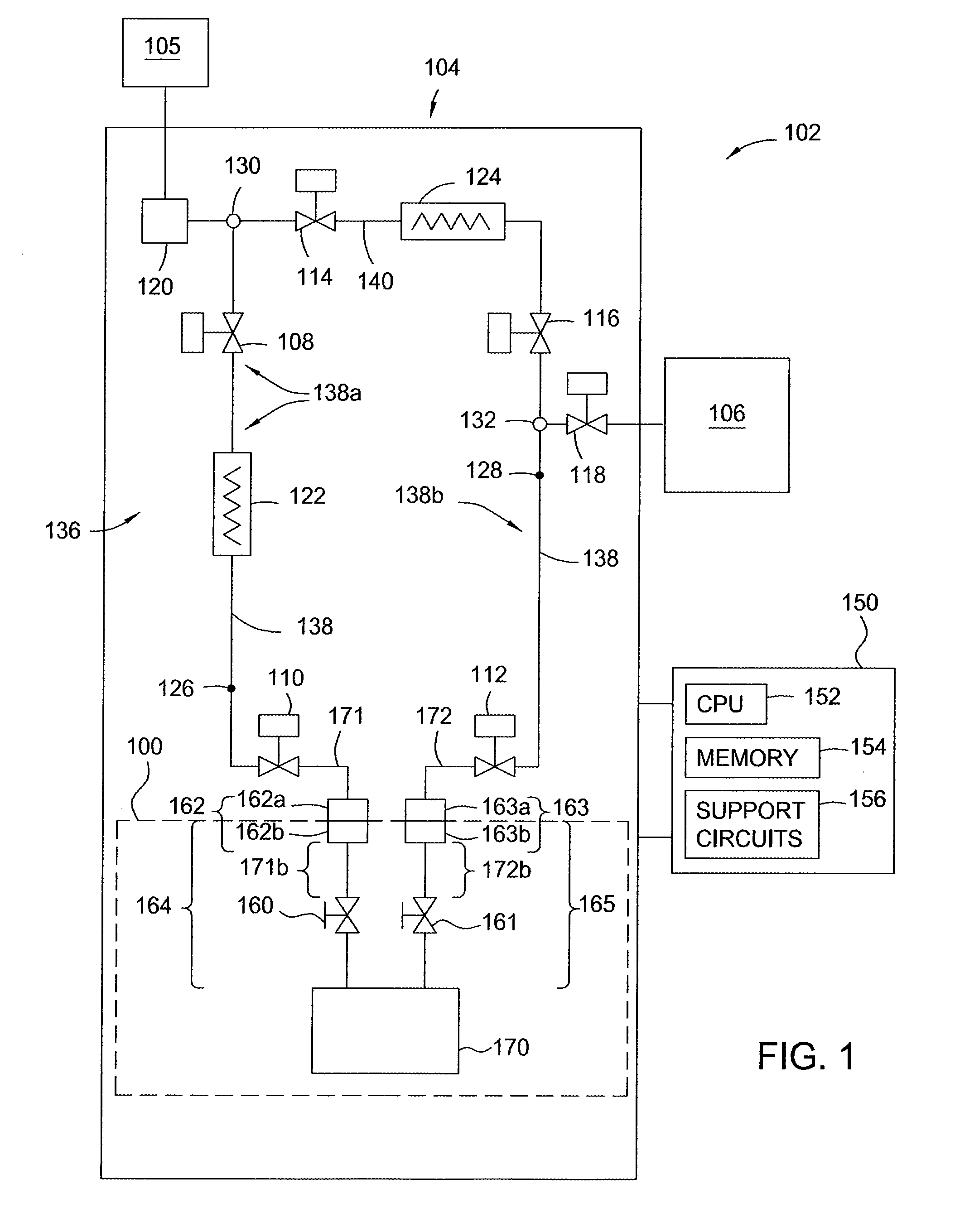
[0038]FIG. 1 is a simplified schematic of process gas delivery system 102 which suitable for producing a process gas containing a chemical precursor and generally includes process chamber 106 and a carrier gas source 105 coupled to gas panel 104, the components of the latter being controlled by a controller 150. Gas panel 104 generally controls the rate and pressure at which various process and carrier gases are delivered to process chamber 106. Process chamber 106 may be a chamber to conduct vapor deposition processes or thermal processes containing a vaporized chemical precursor in liquid, gaseous or plasma state. Process chamber 106 is generally a chemical vapor deposition (CVD) chamber, an atomic layer deposition (ALD) chamber, or a derivative thereof. Examples of process chamber 106 include a PRODUCER® CVD chamber and a DZX® CVD chamber, both available from Applied Materials, Inc., located in Santa Clara, Calif., or an ALD chamber, such as that described in commonly assigned U....


PUM

PropertyMeasurementUnit
temperatureaaaaaaaaaa

Abstract

Embodiments of the invention provide an apparatus and a method for generating a gaseous chemical precursor that may be used in a vapor deposition processing system. In one embodiment, the apparatus contains a valve manifold assembly, which includes a valve assembly body having at least one embedded electric heater, an inlet channel passing through the valve assembly body, a first pneumatic valve and a first manual valve coupled to the valve assembly body and positioned to control fluid flow within the inlet channel, an outlet channel passing through the valve assembly body, and a second pneumatic valve and a second manual valve coupled to the valve assembly body and positioned to control fluid flow within the outlet channel. The valve manifold assembly further contains a bypass channel connected to and between the inlet and outlet channels, and containing a bypass valve positioned to control fluid flow within the bypass channel.

Description

CROSS-REFERENCE TO RELATED APPLICATIONS[0001]This application claims priority to U.S. Provisional Patent Application Ser. No. 61 / 037,271, filed Mar. 17, 2008. Each of the aforementioned related patent applications is herein incorporated by reference in its entirety.BACKGROUND OF THE INVENTION[0002]1. Field of the Invention[0003]Embodiments of the invention relate to an apparatus and a method for storing and delivering chemical precursors, and more particularly, to a heated valve manifold and methods thereof.[0004]2. Description of the Related Art[0005]Integrated circuits have evolved into complex devices that include millions of transistors, capacitors, and resistors on a single chip. The evolution of chip design continually requires faster circuitry and greater circuit density demanding increasingly precise fabrication processes. The precision processing of substrates requires precise control of temperature, rate, and pressure in the delivery of fluids used during processing.[0006]...

Claims


Application Information

Patent Timeline
Patent Type & Authority Applications(United States)
IPC IPC(8): C23C16/44C23C16/54
CPCC23C16/45561C23C16/4481C23C16/45525H01L21/67017
Inventor CHOI, KENRIC T.NGUYEN, SON T.
Owner APPLIED MATERIALS INC
Learn More