Helical hybrid stent

a hybrid stent and helical technology, applied in the field of stents, can solve the problems of increased trauma to the vessel, interference with the vessel's natural tendency to bend and stretch, and the inability of stents with good flexibility to provide sufficient and/or uniform radial support for the vessel wall

Active Publication Date: 2009-09-17
MEDINOL LTD
View PDF108 Cites 33 Cited by
  • Summary
  • Abstract
  • Description
  • Claims
  • Application Information

AI Technical Summary

Benefits of technology

[0009]The present invention provides a helical stent that is longitudinally flexible such that it can easily be tracked down tortuous lumens and does not significantly change the compliance of the vessel after deployment, wherein the stent is relatively stable so that it avoids bending or tilting in a manner that would potentially obstruct the lumen and avoids leaving significant portions of the vessel wall unsupported. The stent of the present invention comprises a helical structure maintained by a polymer fiber layer or other securement. Further, this stent has the radial support of a metal stent combined with longitudinal flexibility, conformability and fatigue resistance to longitudinal repeated bending, compression and twisting, that is much higher than that achievable by metal stents.
[0010]One embodiment of the invention comprises a main stent component combined with a polymer fiber layer such as, for example, a biocompatible material, wherein the polymer fiber layer maintains the tubular shape of the stent while the main component provides structural support both to the vessel and the polymer fiber layer to prevent sagging of the polymer layer into the lumen upon deployment.
[0014]In another embodiment, the main stent component may be designed such that each undulating coil directly abuts an adjacent undulating coil of the helical structure so that the space between cycles is minimized; that is, the undulating pattern is nestled into an adjacent, substantially similar undulating pattern at different cycles of the helical coils. In this manner, the helical coils of the stent provide enhanced coverage of the wall of the lumen without loss of overall stent flexibility. Because the helical coils may be nestled into one another without directly touching each other, the overall flexibility of the formed stent is unaffected by the proximity of different cycles of the helical coils. This arrangement also prevents potential sagging of the polymer layer connecting the helix. The nestling of elements in adjacent coils can be either by nestling of undulating structures as described above or by nestling of any type of connected elements, connected to the undulating structure. These elements can be straight—stick like—elements aligned with the longitudinal direction of the stent or slanted or curved relative to it.

Problems solved by technology

When the stent has a higher longitudinal rigidity than the vessel in which it is implanted, increased trauma to the vessel may occur at the ends of the stent, due to stress concentrations on account of the mismatch in compliance between the stented and un-stented sections of the vessel, or otherwise, the rigid stent may interfere with the vessel's natural tendency to bend and to stretch.
Conversely, stents with good flexibility often lack sufficient and / or uniform radial support for the vessel wall.
Another problem in the art arises when trying to simplify the manufacturing process of a stent to reduce costs yet prevent manufacturing defects, while still producing a stent with uniformly high flexibility and sufficient radial support.

Method used


Image

  • Helical hybrid stent
  • Helical hybrid stent
  • Helical hybrid stent

Examples


Embodiment Construction

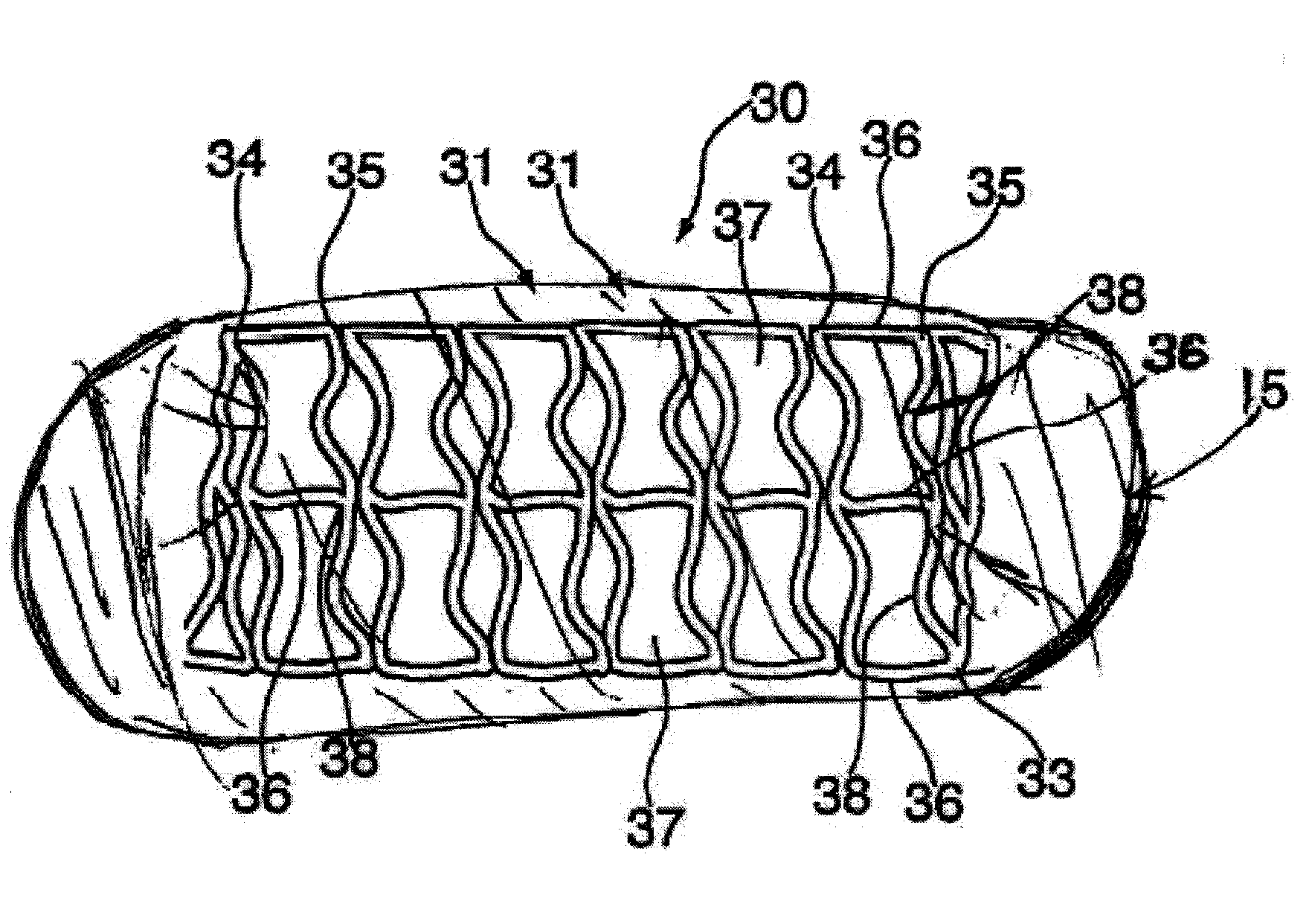
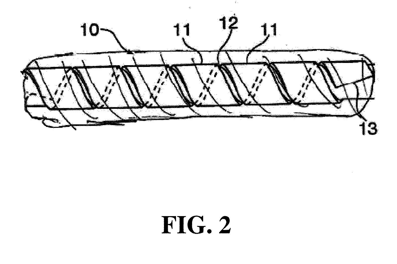
[0025]This invention provides a new class of intraluminal prosthetic devices defined as helical hybrid stents. In particular, the stents of the present invention comprise a main stent component in the form of a helical tubular structure. The main stent component may be held in its coiled position by a second component, securing the helical coils into a tubular structure. The second component may be one or more of a variety of means for securing the main stent component in the tubular form. The second component may be, for example, weld points, interlocking means and / or a polymer. In one embodiment, the second component comprises a polymer or polymer fibers which wraps around or embeds itself in the coiled main stent component. The elastic range of the polymer fiber layer must be sufficient to allow expansion of the stent and maximal bending during and after implantation without reaching the elastic limit.

[0026]The stent of the present invention may be balloon expandable or self-expa...


PUM

PropertyMeasurementUnit
temperatureaaaaaaaaaa
speedaaaaaaaaaa
velocityaaaaaaaaaa

Abstract

An expandable helical stent is provided, wherein the stent may be formed of an amorphous metal alloy or other non-amorphous metal with a securement. The stent is formed from flat or tubular metal in a helical coiled structure which has an undulating pattern. The main stent component may be formed of a single helically coiled component. Alternatively, a plurality of helically coiled ribbons may be used to form a stent heterogeneous in design, material, or other characteristic particular to that stent. The helical tubular structure may be secured with a securement, such as a weld, interlock or a polymer, to maintain the helical coils in a tubular configuration. The helical coils of the main stent component may be spaced apart or nestled to each other. The nestling of the undulation of adjacent helical coils contributes to maintaining the tubular shape of the helically coiled stent. In addition, the nestling of helical coils may prevent the polymer layer from sagging at any point between cycles of the helical coils.

Description

[0001]This application is a continuation-in-part of application Ser. No. 11 / 377,769 filed on Mar. 15, 2006 which is a continuation-in-part of application Ser. No. 11 / 331,639, filed on Jan. 13, 2006, now abandoned, which is a continuation-in-part of application Ser. No. 10 / 860,735, filed on Jun. 3, 2004, now abandoned, which is a continuation-in-part of application Ser. No. 10 / 116,159, filed on Apr. 5, 2002, now abandoned, which is a continuation application of Ser. No. 09 / 204,830, filed on Dec. 3, 1998, now abandoned. application Ser. No. 11 / 377,769 is also a continuation-in-part of application Ser. No. 10 / 607,604, filed on Jun. 27, 2003, now abandoned. The entirety of these priority applications is hereby incorporated in toto by reference.FIELD OF THE INVENTION[0002]The invention relates generally to stents, which are intraluminal endoprosthesis devices implanted into vessels within the body, such as blood vessels, to support and hold open the vessels, or to secure and support othe...

Claims


Application Information

Patent Timeline
Patent Type & Authority Applications(United States)
IPC IPC(8): A61F2/06
CPCA61F2/88A61F2/91A61F2250/0068A61L31/022A61F2220/0025Y10T29/49764A61F2220/0058A61F2/89A61L31/10C08L27/18A61F2/07A61F2002/072A61L31/14A61F2230/0091A61F2/885A61F2250/0067A61F2220/005A61K31/436A61L31/06A61L31/146A61L31/16A61L2300/416C08L75/04A61F2002/075A61F2/915A61F2002/91583A61L31/048
Inventor RICHTER, JACOB
Owner MEDINOL LTD
Why Eureka
Try Eureka