

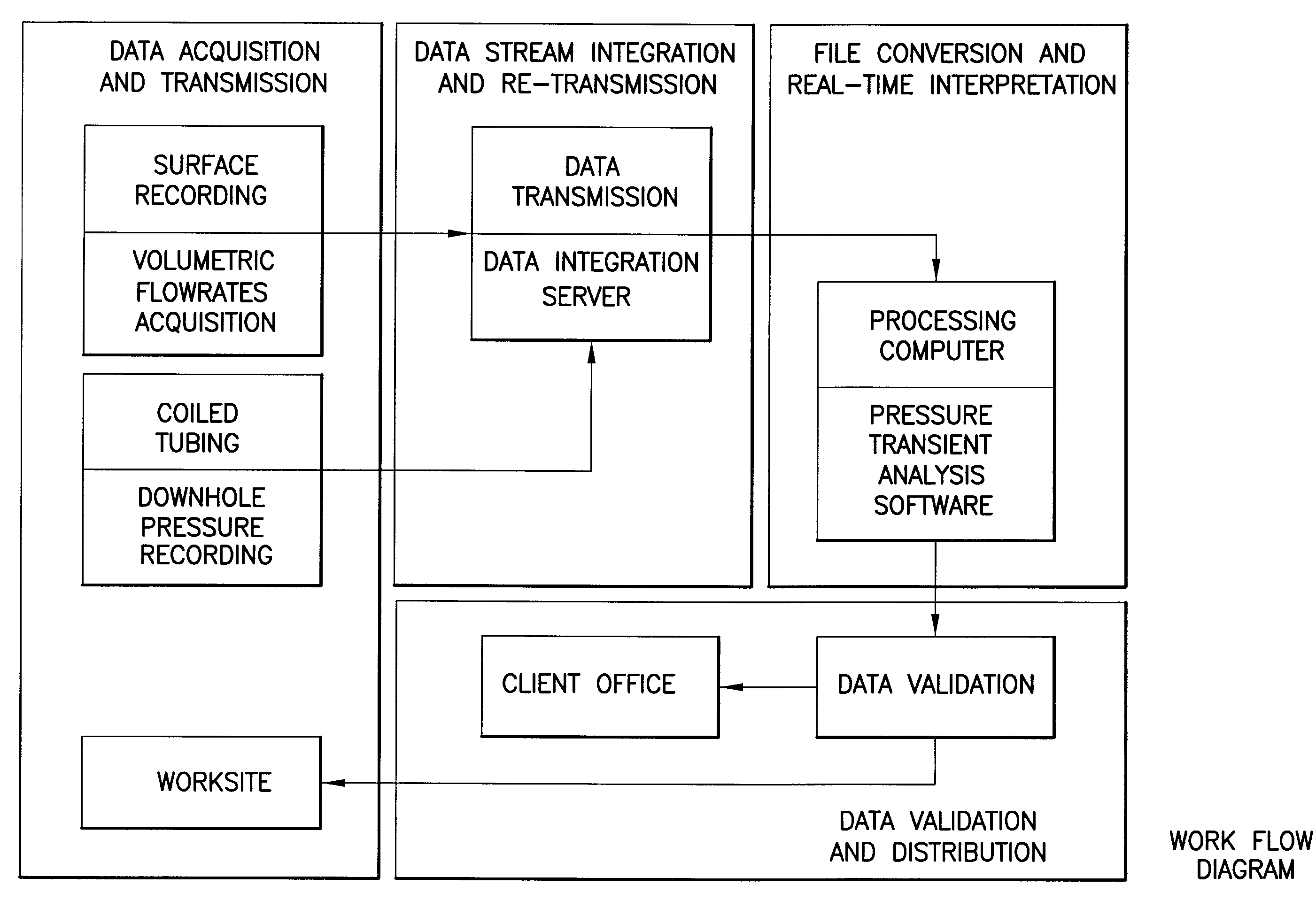
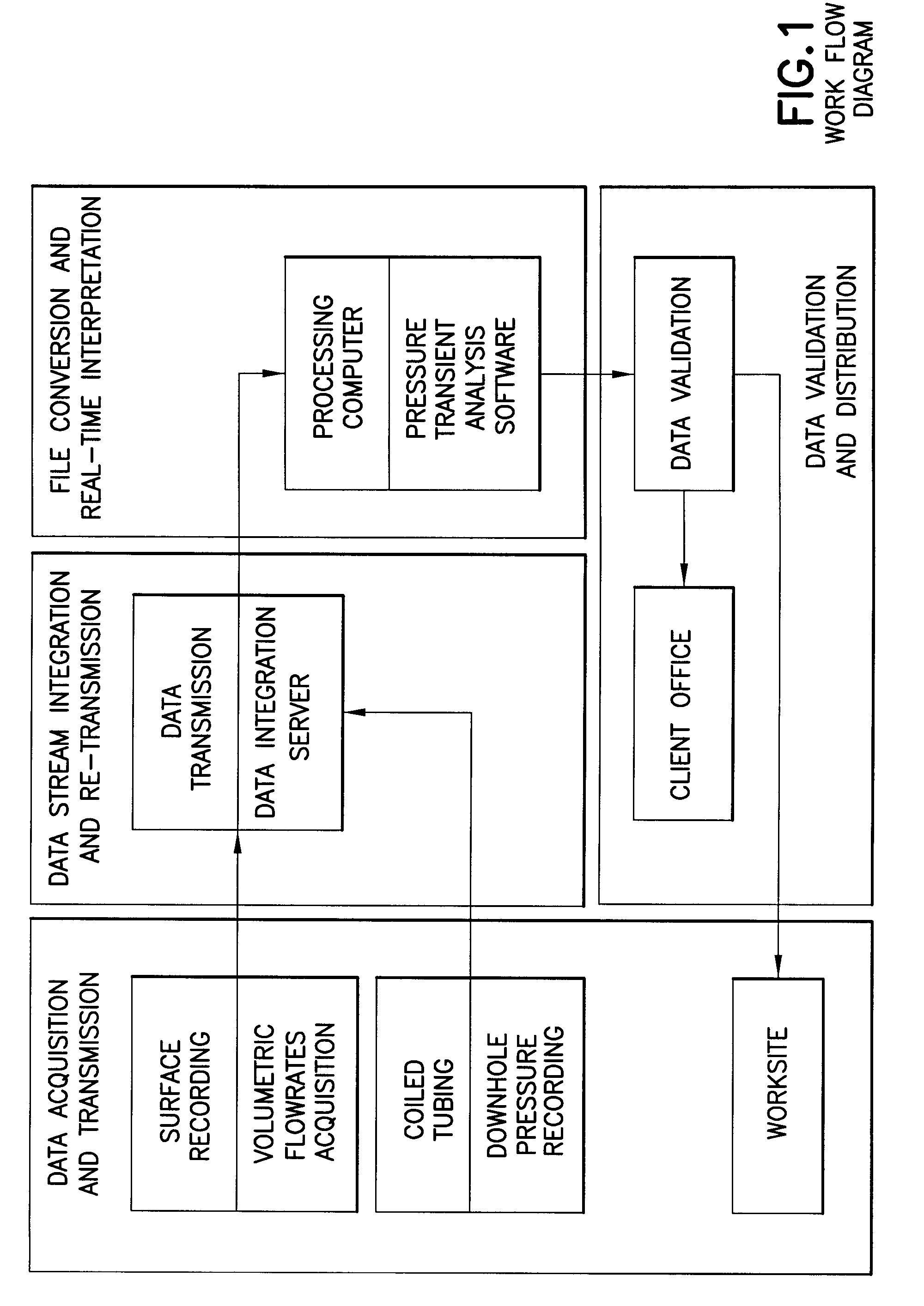
Data gathering, transmission, integration and interpretation during coiled tubing well testing operations
a technology applied in the field of hydrocarbon well testing, can solve the problems of complex operation, high cost of process, and significant rig time, and achieve the effect of transmission, reducing the cost of process, and improving the accuracy of data gathering
- Summary
- Abstract
- Description
- Claims
- Application Information
AI Technical Summary
Benefits of technology
Problems solved by technology
Method used
Image

Examples
Embodiment Construction
[0017]Historically, pressure transient analysis is completed days or even weeks following the stimulation and well testing of a particular well. Some of the contributing factors to this time delay may be the remoteness of the well being tested, combining data sets from different sources, and synchronizing (same sampling time, for example) the data sets to be able to upload it into the interpretation software used. Well sites are often in remote locations far from the staff that will perform the interpretation and modeling. The data typically goes through an extensive process of transmittal, synchronization, validation, and integration, among other processes, before making its way to the staff that will interpret and model the data. Much time can be saved and efficiency to be gained by offering integrated downhole and surface data sets streamlined onto a processing unit with near real-time data updating.
[0018]The present invention can facilitate near real-time pressure transient anal...
PUM
 Abstract
Description
Claims
Application Information