Fuel saving food cooker and water heater arrangement

a fuel-saving, food-cooking technology, applied in drying machines, drying chambers/containers, light and heating equipment, etc., can solve the problems of affecting the efficiency of the drying machine, the design of the conventional machine is also complicated, and the price is much higher than the average person's ability to afford, and achieves poor efficiency and slow speed

Inactive Publication Date: 2009-09-24
BO HU JIE
View PDF13 Cites 15 Cited by
  • Summary
  • Abstract
  • Description
  • Claims
  • Application Information

AI Technical Summary

Benefits of technology

[0008]In order to purify the air exiting from the PTC outlet, an ultraviolet ray sterilizer can be mounted on one side of the PTC outlet. Furthermore, in order to prevent people from being hurt by the ultraviolet ray produced by ultraviolet ray light, the light cap is provided on the upper portion of the ultraviolet ray light.
[0009]The hanger plate having a fastener is provided at the four corners of the base for supporting the base. The division plate for the warm air cushioning chamber and the top net plate are provided from top to bottom of the hanger plate respectively through the connecting block, wherein the division plate for the warm air cushioning chamber forms the warm air cushioning chamber with the protection plate of the warm air channel in the lower parts and forms the cloth drying chamber, and the distance between each of them is larger than 60 cm so as to guarantee the temperature of the air coming out from the hot air channel is fully decreased.
[0010]The effect of the present invention is that the steam rising from the bottom of the base is scientifically going up following the natural rule: the hot air is usually going up. That is it shows the innovation structure to overcome the conventional problems in conventional technology and provide a safe, faster way to dry clothes. Furthermore, the procedure of drying cloth is controllable. In order to prevent energy waste, the bottom portion of the cover and the upper portion of the base are sealed together to achieve the goal of energy saving. On the other hand, a couple of small holes are provided at the upper portion of the cover as an output of the steam from bottom to top for improving the clothes drying efficiency. The temperature and humidity within the warm air cushioning chamber are measured by temperature sensor and humid sensor, and response the result for the main control such that the clothes drying appliance is capable of automatically turning off the power while the temperature of the clothes drying appliance is not normal or the cloth is dry enough to achieve the goal of energy saving. The efficiency of drying cloth is high, and the drying speed is fast. Furthermore, safe is guaranteed while hanging clothes fall down.

Problems solved by technology

Nowadays, due to the limitation of weather and location, more and more people have to use the drum-type dryer or the washing machines with dryer function, which are found in every appliance store.
Even though the intelligence design and safety standards of the both types of conventional dryer product meet the national requirements, there are still drawbacks as follows.
The drum-type dryer easily causes wrinkles and damages to the clothes during the rotation operation that needs time to be ironing thereafter.
Moreover, the design of the conventional machine is also complicated that the price is much higher than what the average person can afford.
In addition, it slows down the drying speed, adversely affects the drying ability and is energy consuming.
There is no way to control the conditions including the temperature and humidity inside the dryer.
If the hanging large clothes after dried falls by accident and blocks the exit vent, damages to the clothes and safety hazard may occur.

Method used


Image

  • Fuel saving food cooker and water heater arrangement
  • Fuel saving food cooker and water heater arrangement
  • Fuel saving food cooker and water heater arrangement

Examples


Embodiment Construction

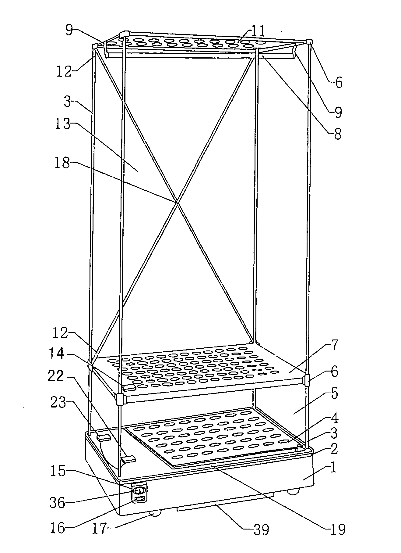
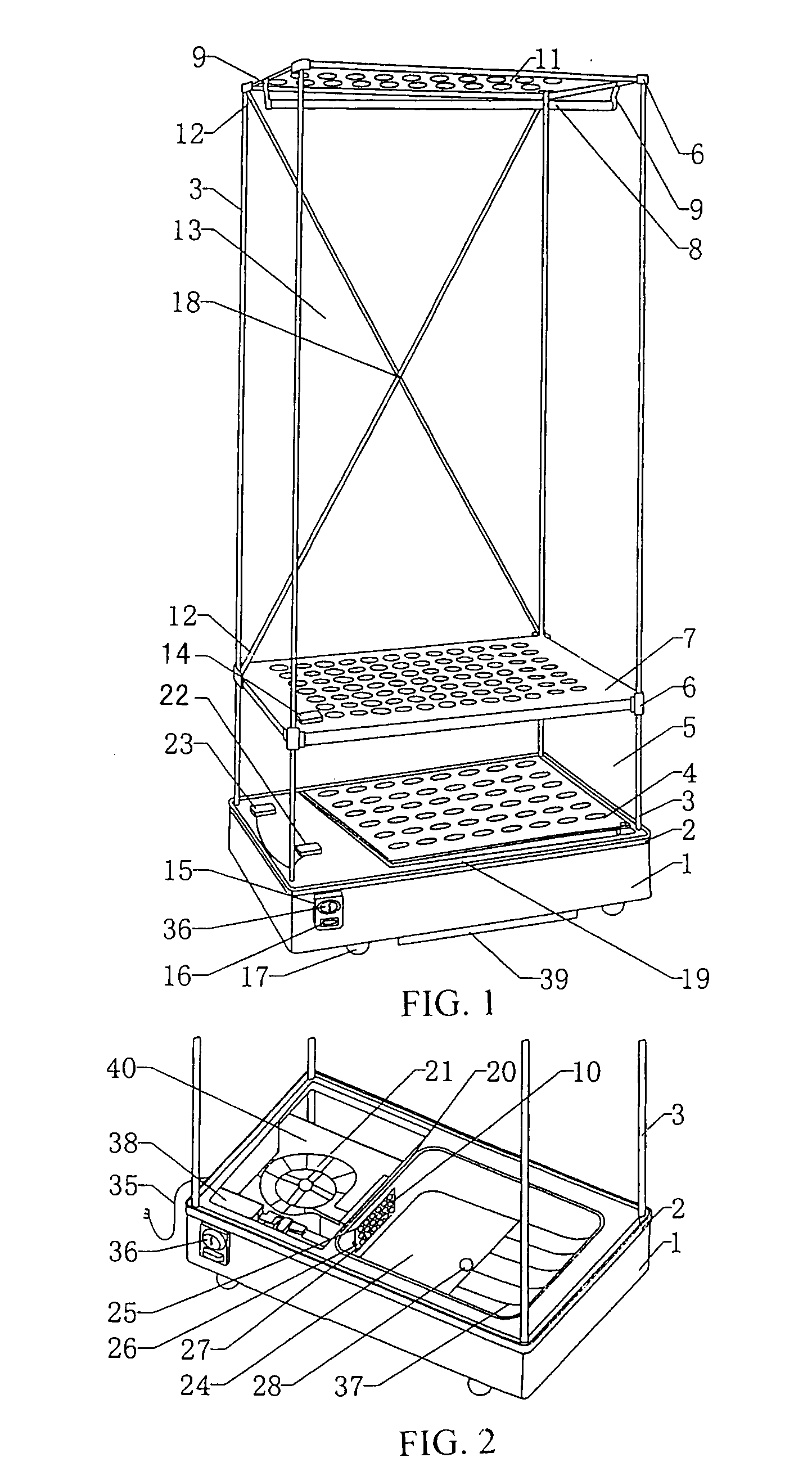
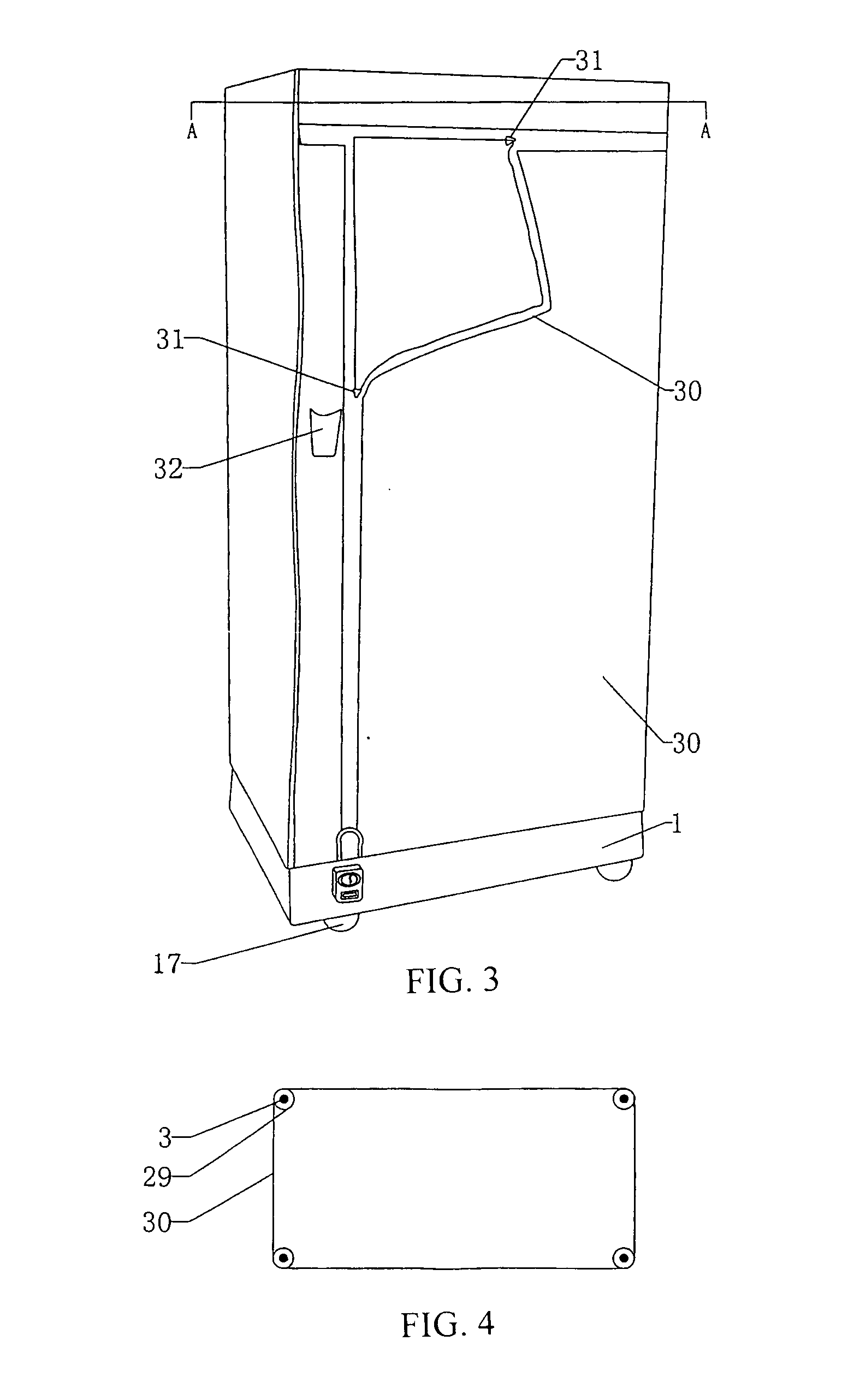
[0019]Referring to FIGS. 1 to 5 of the drawing, a cabinet-type clothes drying appliance according to a preferred embodiment of the present invention is illustrated, which comprises a base 1, a moveable wheels 17 providing at the base 1, a frame, a cover 30, and a control unit, wherein a protruding stand 2 is provided at a boundary of the base for fastening the cover 30 along a lower opening thereof. The base 1 further comprises a humidity sensor 14 and an ozone sterilizer 23. A waterproof stand 19 is provided at the boundary of the base 1. A front side of the base 1 provides a control unit switch 36, a humidity sensor 15 and a storage of remote control 16. Also, a main control 38 and a wind turbine 22 are provided at one side of the base 1 to form a heat source, and that a hot wind channel 24 having a water outlet 28 is provided at another side of the base 1. A divisional plate 20 is provided between two sides of the base 1. A hot wind channel 24 comprises a protection plate of the ...


PUM


Abstract

A clothes drying cabinet which consists of a base, a frame, a cover and a control unit is disclosed. A heat source, a warm air cushion chamber and a clothes drying chamber are provided inside the clothes drying cabinet. The heat source comprises a fan motor and a PCT heating element. The frame is positioned on the base and supported by the hanger braces. The division plate for the warm air cushioning chamber forms the warm air cushioning chamber with the protection plate of the warm air channel in the lower parts and forms the cloth drying chamber. The frame is covered outside by the cover. The control unit comprises a control panel and switches. The clothes drying effect can be improved and the drying speed can be increased, furthermore the clothes drying cabinet is safe so that the danger due to clothes falling down can be prevented.

Description

BACKGROUND OF THE PRESENT INVENTION[0001]1. Field of Invention[0002]The present invention relates to a cloth drying appliance, and more particularly to a cabinet type clothes drying appliance.[0003]2. Description of Related Arts[0004]Nowadays, due to the limitation of weather and location, more and more people have to use the drum-type dryer or the washing machines with dryer function, which are found in every appliance store. Even though the intelligence design and safety standards of the both types of conventional dryer product meet the national requirements, there are still drawbacks as follows. The drum-type dryer easily causes wrinkles and damages to the clothes during the rotation operation that needs time to be ironing thereafter. Moreover, the design of the conventional machine is also complicated that the price is much higher than what the average person can afford. Therefore, an economic drying appliance that is affordable to the public while its safety properties conform ...

Claims


Application Information

Patent Timeline
Patent Type & Authority Applications(United States)
IPC IPC(8): F26B21/08F26B21/06F26B25/06F26B19/00
CPCD06F58/10D06F73/02D06F58/14D06F34/26D06F57/08D06F57/02D06F57/06D06F57/12D06F2105/20D06F2105/30
Inventor JIE BO, HU
Owner BO HU JIE
Why Eureka
Try Eureka