Detection of refrigerant release in co2 refrigerant systems

a technology of refrigerant system and refrigerant temperature, which is applied in the field of refrigerant system, can solve the problems of affecting the reliability of compressors, affecting the performance (capacity and efficiency) of refrigerant systems, and undesired temperature rise of components, so as to prevent component damage or compromise

Inactive Publication Date: 2009-09-24
CARRIER CORP
View PDF15 Cites 8 Cited by
  • Summary
  • Abstract
  • Description
  • Claims
  • Application Information

AI Technical Summary

Benefits of technology

[0008]In disclosed embodiments of this invention, devices are provided to detect the release of a refrigerant to the environment during operation, storage or transportation. These devices may include a pressure relief valve, a burst disk, etc., to provide an indication that there may b...

Problems solved by technology

This can affect the performance (capacity and efficiency) of the refrigerant system, and undesirably raise the temperature of the components that are cooled by the refrigerant.
As an example, the compressor and its motor are o...

Method used


Image

  • Detection of refrigerant release in co2 refrigerant systems
  • Detection of refrigerant release in co2 refrigerant systems

Examples


Embodiment Construction

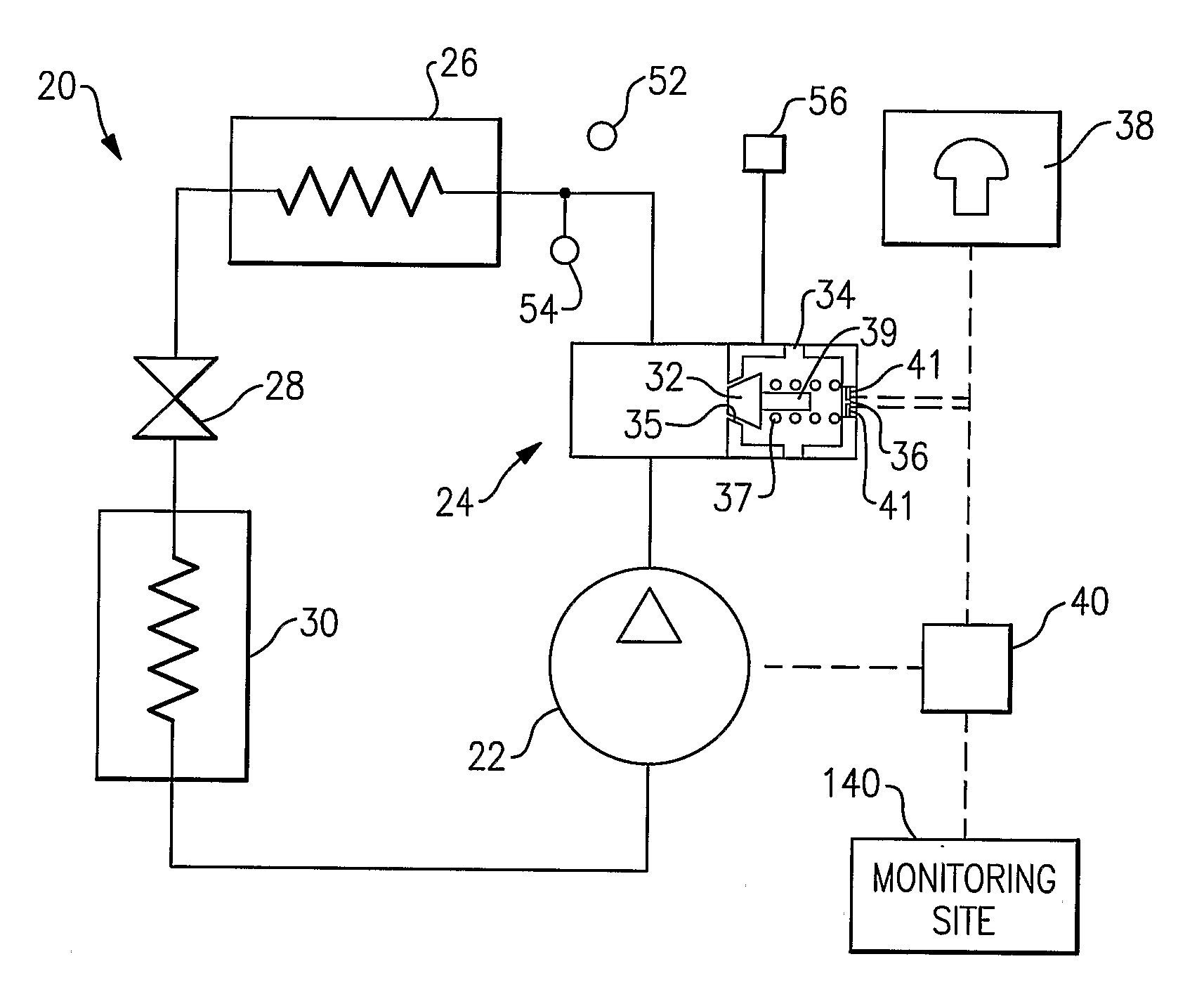
[0015]A basic refrigerant system 20 incorporates a compressor 22 delivering compressed refrigerant downstream, through a pressure relief valve assembly 24, into a heat rejecting heat exchanger 26, through an expansion device 28, to an evaporator 30 and back to the compressor 22. The refrigerant system 20 operates with an environmentally friendly natural refrigerant, such as carbon dioxide (also known as CO2 or R744). Further, the refrigerant system 20 depicted in FIG. 1 is a basic refrigerant system, and many options and features could be added to the system schematic to enhance performance and reliability. All these configurations are within the scope and can equally benefit from the present invention. As known, the heat rejecting heat exchanger 26 could serve as a condenser in subcritical operation or as a gas cooler in transcritical operation.

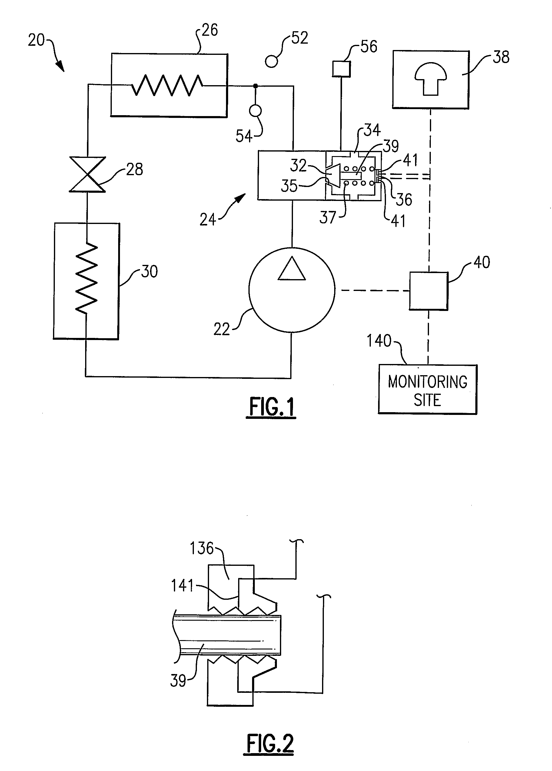
[0016]Also, as known, the pressure relief valve assembly 24 is a safety device and allows the release of at least a portion of refrigerant ...


PUM


Abstract

A refrigerant system utilizes environmentally friendly natural refrigerant such as carbon dioxide. A pressure relief mechanism such as pressure relief valve is incorporated into the refrigerant system design to allow for at least some amount of refrigerant to be released to atmosphere to provide safe operation or comply with agency regulations if pressure within the refrigerant system exceeds a certain limit. This release can occur during refrigerant system storage, transportation or operation. A detection device such as an electrical circuit is included into the refrigerant system design to provide an indication that pressure relief valve has opened, such that the determination can be made by a refrigerant system control or an operator whether the refrigerant system needs to be recharged and whether it can continue its normal operation, narrow its operational envelope or shut down until the refrigerant charge can be restored.

Description

BACKGROUND OF THE INVENTION[0001]This application relates to a refrigerant system charged with an environmentally benign refrigerant, such as CO2, and having an identification device in place to detect when an overpressurization of a refrigerant system has caused release of at least some amount of refrigerant to the environment.[0002]Refrigerant systems are known, and are utilized to condition indoor environments by maintaining the temperature and / or humidity of a secondary fluid within the required tolerance band or specification. As a common example, an air conditioning system cools / dehumidifies air to be delivered into a climate controlled indoor environment.[0003]Historically, refrigerant systems have operated in the subcritical range and utilized hydrochlorofluorocarbons (HCFCs), such as R22, and more commonly hydrofluorocarbons (BFCs), such as R134a, R410A and R407C (so-called Freons) as refrigerants. Although BFC refrigerants are more environmentally friendly than the chlorin...

Claims


Application Information

Patent Timeline
IPC IPC(8): F25D3/00F25B1/00G01K13/00
CPCF25B9/008F25B49/005F25B2309/061F25B2700/21152F25B2700/1931F25B2700/2106F25B2600/01
Inventor LIFSON, ALEXANDERTARAS, MICHAEL F.
Owner CARRIER CORP
Why Eureka
Try Eureka