Bicycle Fork and Steering Tube

a technology of steering tube and bicycle fork, which is applied in the direction of steering device, friction roller based transmission, cycle equipment, etc., can solve the problems of high construction complexity, particularly difficult to meet the needs of users, and the hole at the base of the steering tube of the finished fork is open, so as to reduce both weight and stress, the effect of superior construction

Inactive Publication Date: 2009-09-24
BEARCORP
View PDF19 Cites 4 Cited by
  • Summary
  • Abstract
  • Description
  • Claims
  • Application Information

AI Technical Summary

Benefits of technology

[0013]The present invention provides unique, improved construction features that remedy the deficiencies of prior bicycle front wheel fork and steering tube systems. The invention provides a bicycle with a wheel fork and steering tube assembly that has a superior, weight-reducing construction, and which reduces both weight and stress at the lower end of the steerer tube and at the lower ends of the bicycle fork legs. Moreover, a hollow preload bolt is provided that has a much larger cable routing access passageway than conventional systems.
[0017]By constructing the interface between the fork legs and the steerer tube in this manner, a potential snag or fouling risk is avoided by closing off the lower end of the steerer tube. Furthermore, this construction avoids the excessive weight in the steerer tube that would otherwise exist due to the extra material within the circumference of the steerer tube interface openings at the upper end of the fork legs. By trimming and forming the lower end of the steerer tube to conform to the area encompassed within the steerer tube interface openings at the upper ends of the fork legs, a smoother profile results, along with a reduction in weight of the steerer tube. The steerer tube is trimmed to remove lightly stressed material that lies within an area that is stiffened by the welded upper ends of the fork legs.
[0019]Material is also left on the steerer tube to form a closed bottom to help support the welded upper ends of the fork legs.
[0022]With the construction of the present invention in which the dropouts are formed directly in the lower ends of the tubular fork legs, a considerable reduction of weight is achieved. Moreover, by forming the dropouts in the lower ends of the fork legs so they are on the axis of the leg tubing, undesirable torsional stresses and other stresses on the fork legs are minimized. The dropout support insert that is employed extends up inside the fork leg to brace the dropout to the tubular portion of the fork leg above it, while also providing support against damage and crushing. The construction of the dropout directly in the lower end of each fork leg allows the dropouts to be substantially thicker, therefore more resistant to bending, while avoiding the addition of a large amount of excess weight to the bicycle fork and steering tube assembly.
[0024]A driving wrench, usually one that is hexagonal in shape, may be engaged in the radially offset wrench socket to rotate the preload bolt to tighten or loosen it from the upper end of the steerer tube. By locating the socket off center the cross-sectional area of the cable routing passageway through the hollow preload bolt is increased substantially, and therefore the weight of the preload bolt is reduced. Furthermore, this increased cable passageway allows the preload bolt to be fully removed without disconnecting the bicycle brake cable from the front brake caliper adjustment assembly.
[0025]By configuring the hex socket off center from the axis of alignment of the preload bolt, it is possible to create a much wider brake cable routing passage through the preload bolt than is possible in conventional preload bolt designs. This provides space for the brake cable to easily pass through the large brake cable routing opening next to the hexagonal wrench socket. As a result, the hexagonal socket is never blocked and can be the sole means of adding bolt tension. Because the external wrench flats are no longer required, this construction allows the outer profile of the bolt to be much lower and smoother. Furthermore, the brake cable routing passage can be large enough to accept the larger parts of the brake cable assembly so that servicing and part replacement can be preformed without disassembling the brake cable assembly from the front brake caliper.

Problems solved by technology

These disadvantages are particularly pronounced in the case of BMX bicycles, in which reduced weight and reduced complexity of construction are particularly important.
The “unicrown” configuration results in a open hole at the base of the steerer tube of the finished fork.
This open hole can become fouled with debris that might impede the rotation of the front bicycle wheel that rotates about the front wheel axis within the fork.
Furthermore, this structure allows for relatively large, localized deformations under loads, thus resulting in metal fatigue and ultimately metal failure.
As a result, the finished bicycle front wheel fork and steering tube combination is excessively heavy.
Due to the off center stresses that result from torque forces acting relative to the plane of alignment of the fork legs, the entire lower fork assembly, specifically the fork legs, the dropout flanges and the welds that join the dropout flanges to the lower ends of the fork legs must be very sturdy and are unduly heavy.
Lighter weight dropout flanges tend to be thinner and significantly weaker than desired.
The brake cable passage created conflicts with the “top bolt” which is required for setting up the headset that holds the bicycle handlebars and which bears tension.
That is, the conventional hollow bolt system relies upon a large, external hexagonal configuration on a low bolt head or a smaller hex head that protrudes upwardly in an undesirable way.
However, with the prevalent existing standard headset sizes there is insufficient room to keep a hexagonal socket head central while running the cable eccentrically down through the hollow bolt.
A common solution to this is to run the cable through the hexagonal socket itself, but this renders the socket head unusable until the brake cable has been removed.
Furthermore, with the hex head top bolts most widely utilized, it is not possible to pass a brake cable assembly through intact.
Therefore, any replacement of headset parts, stem, or frame parts, generally requires a labor intensive disassembly of the front brake cable adjustment setup at the front braking caliper.

Method used


Image

  • Bicycle Fork and Steering Tube
  • Bicycle Fork and Steering Tube
  • Bicycle Fork and Steering Tube

Examples


Embodiment Construction

[0044]The detailed description set forth below in connection with the appended drawings is intended as a description of presently-preferred embodiments of the invention and is not intended to represent the only forms in which the present invention may be constructed or utilized. The description sets forth the functions and the sequence of steps for constructing and operating the invention in connection with the illustrated embodiments. However, it is to be understood that the same or equivalent functions and sequences may be accomplished by different embodiments that are also intended to be encompassed within the spirit and scope of the invention.

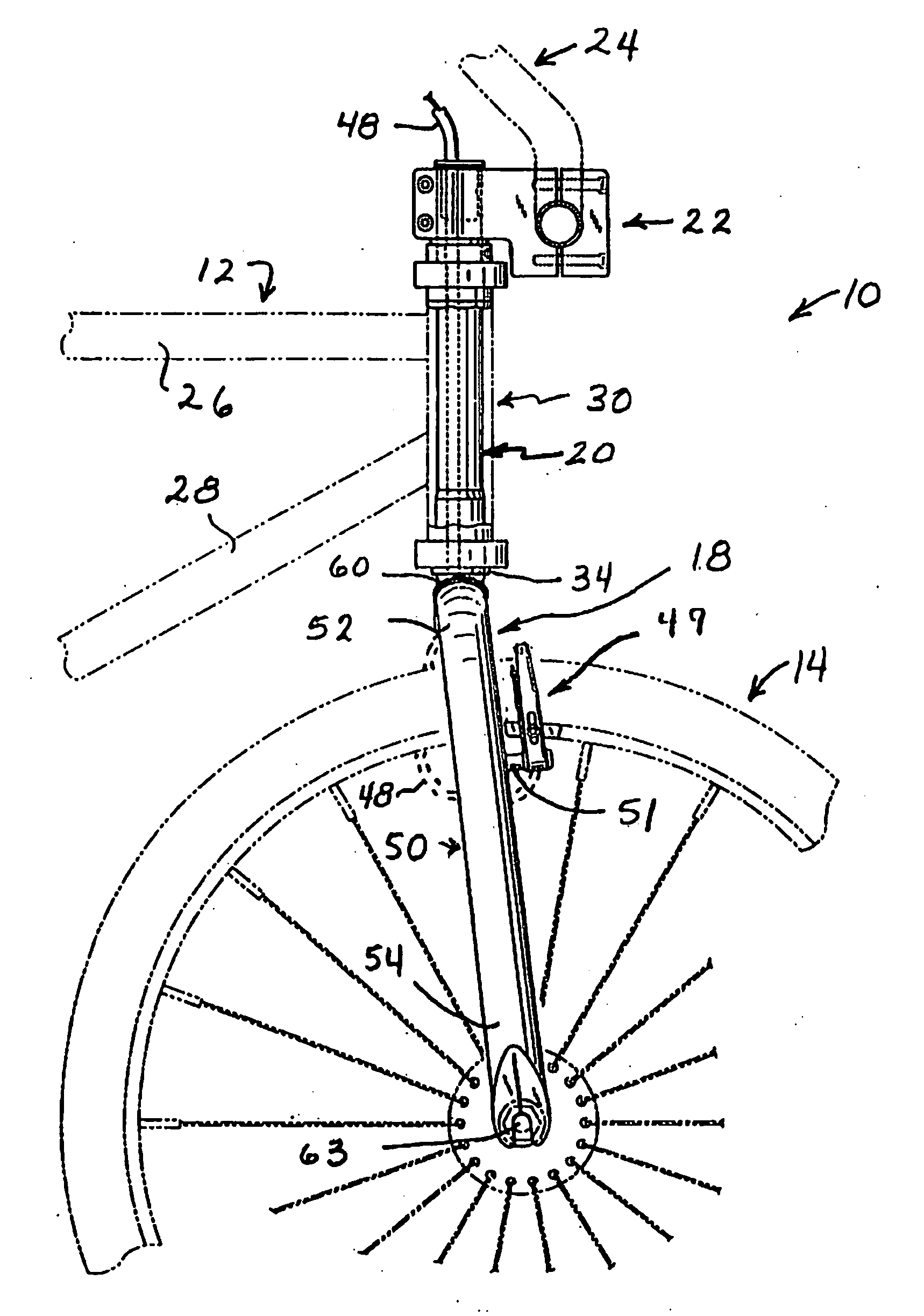
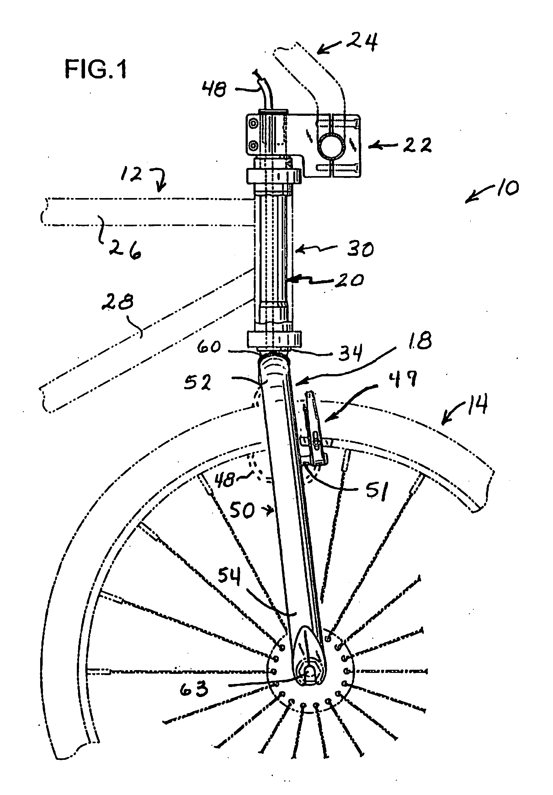
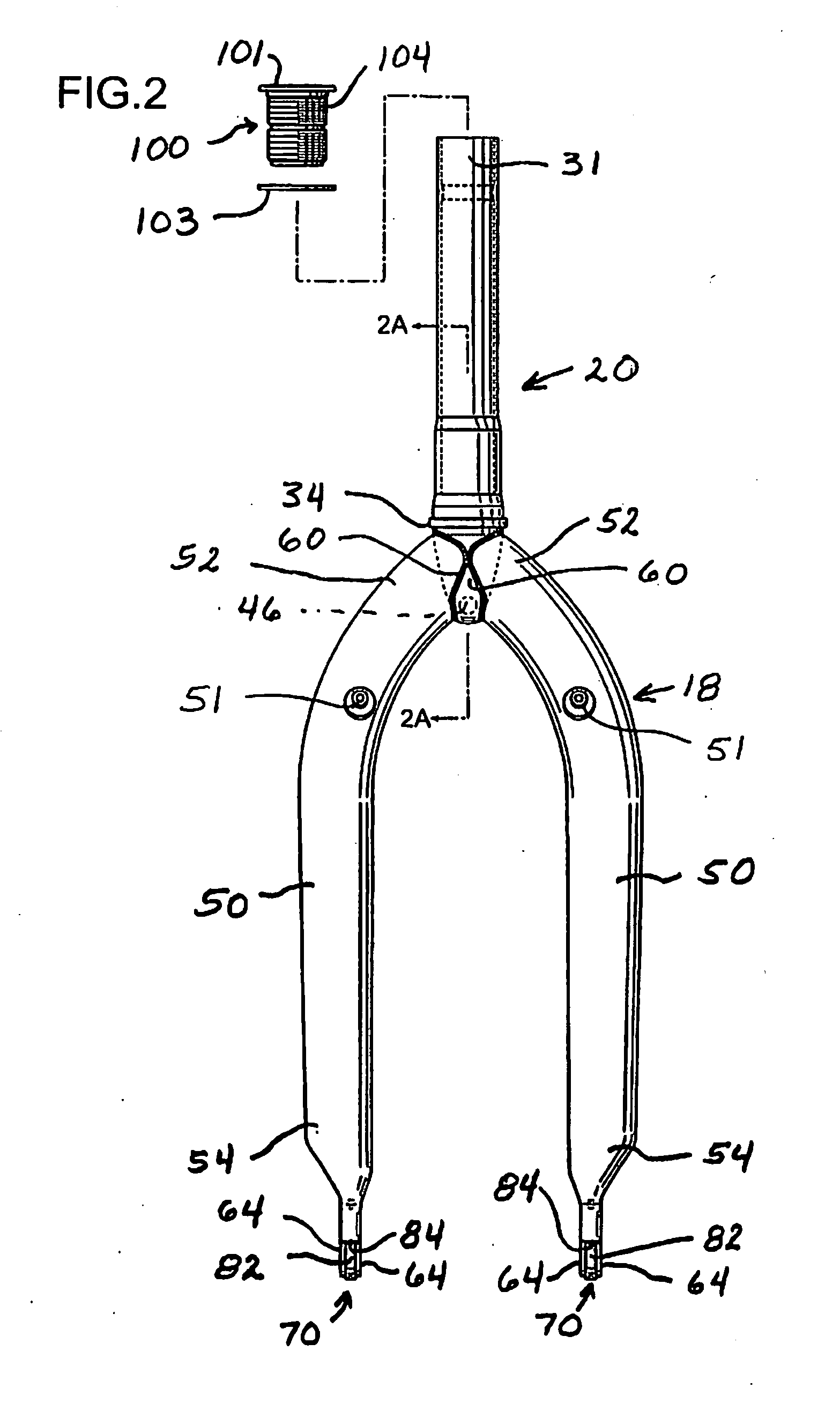
[0045]FIG. 1 illustrates the front portion of a BMX bicycle 10, which includes a conventional bicycle framework illustrated partially in phantom at 12, a front bicycle wheel illustrated in phantom at 14, and the combination of a bicycle fork and steering tube assembly indicated generally at 16 in FIG. 2. The assembly 16 includes a bicycle f...


PUM


Abstract

A combination bicycle fork and steering tube assembly is formed with a pair of downwardly directed, mutually converging end closure tabs that are bent over into abutment and welded together to define peripherally enclosed fork openings at the ends of the steerer tube. The upper ends of the hollow fork legs are configured to follow the surface contours of the lower end of the steerer tube and are welded to the end closure tabs about the circumferences of the enclosed fork openings at the lower end of the steering tube. The front wheel axle dropouts are formed directly in the lower ends of the fork legs, which include internal dropout support inserts. The dropout support inserts are sandwiched in between a pair of flat, mutually parallel dropout tabs defined directly in the lower ends of the fork legs.

Description

CROSS-REFERENCES TO RELATED APPLICATIONS[0001]This patent application is a continuation and claims the benefit of U.S. patent application Ser. No. 11 / 488,404 filed Jul. 19, 2006 for Bicycle Fork and Steering Tube, which application is incorporated here by this reference.TECHNICAL FIELD[0002]This invention relates to a bicycle fork and steering tube construction with particular application to BMX bicycles.BACKGROUND ART[0003]Bicycles have historically be constructed with a cylindrical steerer tube having an upper end joined to the bicycle handlebars, and a lower end to which a bicycle front wheel fork is rigidly fastened. The steerer tube is rotatable within a hollow, cylindrical head tube which forms a part of the bicycle frame and which is located at the front of the bicycle frame. The rider rotates the steerer tube by turning the handlebars to the left or right in order to turn the front wheel fork to the left or right. By altering the orientation of the front wheel relative to th...

Claims


Application Information

Patent Timeline
Patent Type & Authority Applications(United States)
IPC IPC(8): B62K21/02
CPCB62K21/18B62K21/02B62J11/13
Inventor FRENCH, GEORGE
Owner BEARCORP
Why Eureka
Try Eureka