
Park system with high/low trip pressure for added failure protection with work brake application

Inactive Publication Date: 2009-09-24
BENDIX COMML VEHICLE SYST LLC
View PDF18 Cites 12 Cited by
  • Summary
  • Abstract
  • Description
  • Claims
  • Application Information

AI Technical Summary

Benefits of technology

[0006]In accordance with one aspect, a pneumatic brake system for a heavy duty vehicle is provided. The heavy duty vehicle has at least one source of pressurized air for pressurizing the brake system, at least one spring brake chamber including a spring brake assembly, and at least one service brake chamber including a service brake assembly. The brake system includes a first control valve, a second control valve and a work brake system. The first control valve is in communication with the source of pressurized air. The first control valve delivers pressurized air to the spring brake chamber and exhausts pressurized air to atmosphere to activate the spring brake assembly when brake system pressure is reduced to a predetermined low trip brake system pressure. The second control valve is in communication with the source of pressurized air and selectively delivers pressurized air to the service brake chamber for application of the service brake assembly. The work brake system is in

Problems solved by technology

Normal operation of certain heavy duty vehicles that make frequent stops in their vocation (i.e., refuse, transit, school transportation and the like) demand frequent parking brake applications in a short period of time, which consume large volumes of compressed air.
Such operations result in excessive brake system wear, undesirably reducing the useful life of the brake system components, and resulting in increased vehicle maintenance and repair costs.
Although the prior art park systems perform their respective functions, such park systems generally operate in an inefficient manner.

Method used


Image

  • Park system with high/low trip pressure for added failure protection with work brake application
  • Park system with high/low trip pressure for added failure protection with work brake application
  • Park system with high/low trip pressure for added failure protection with work brake application

Examples


Embodiment Construction

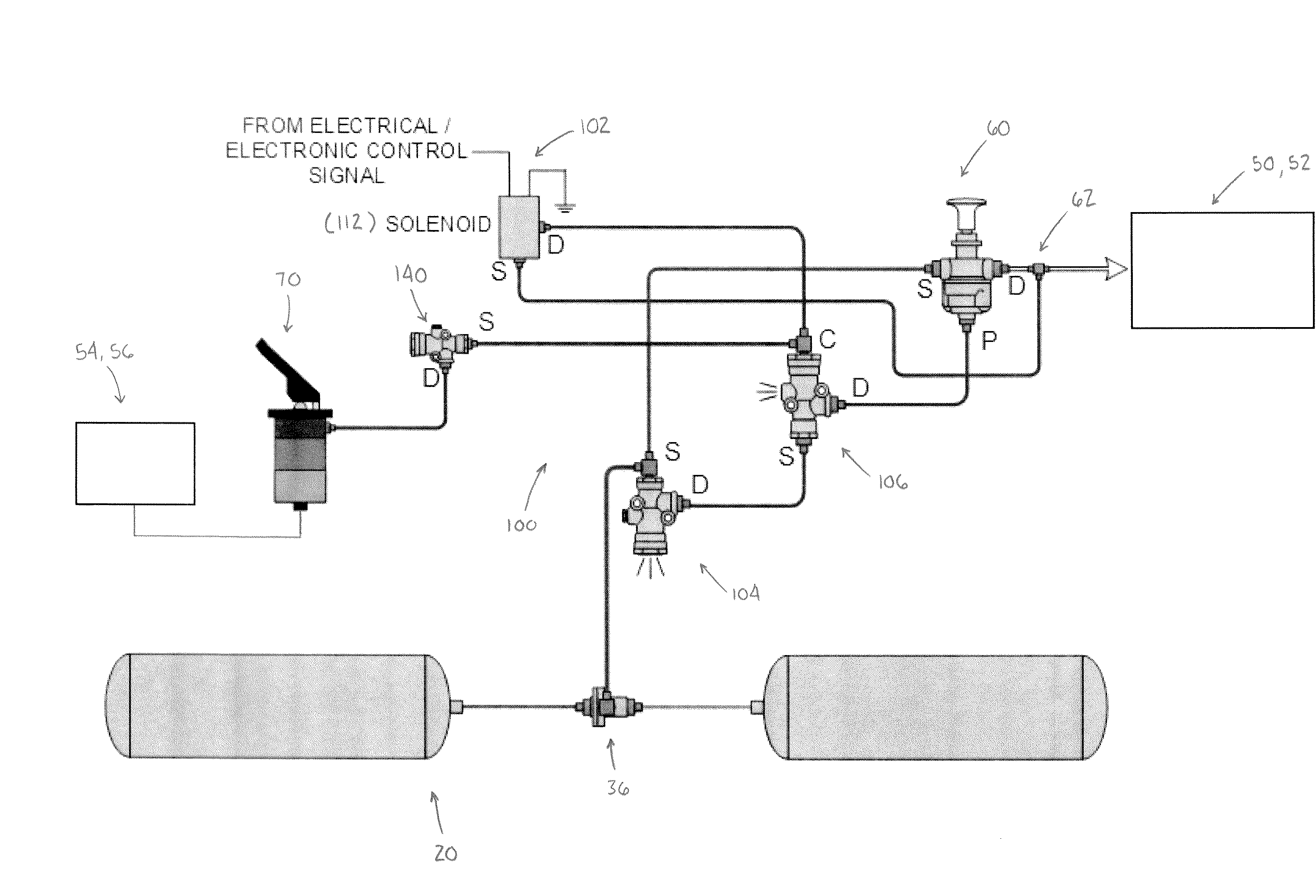
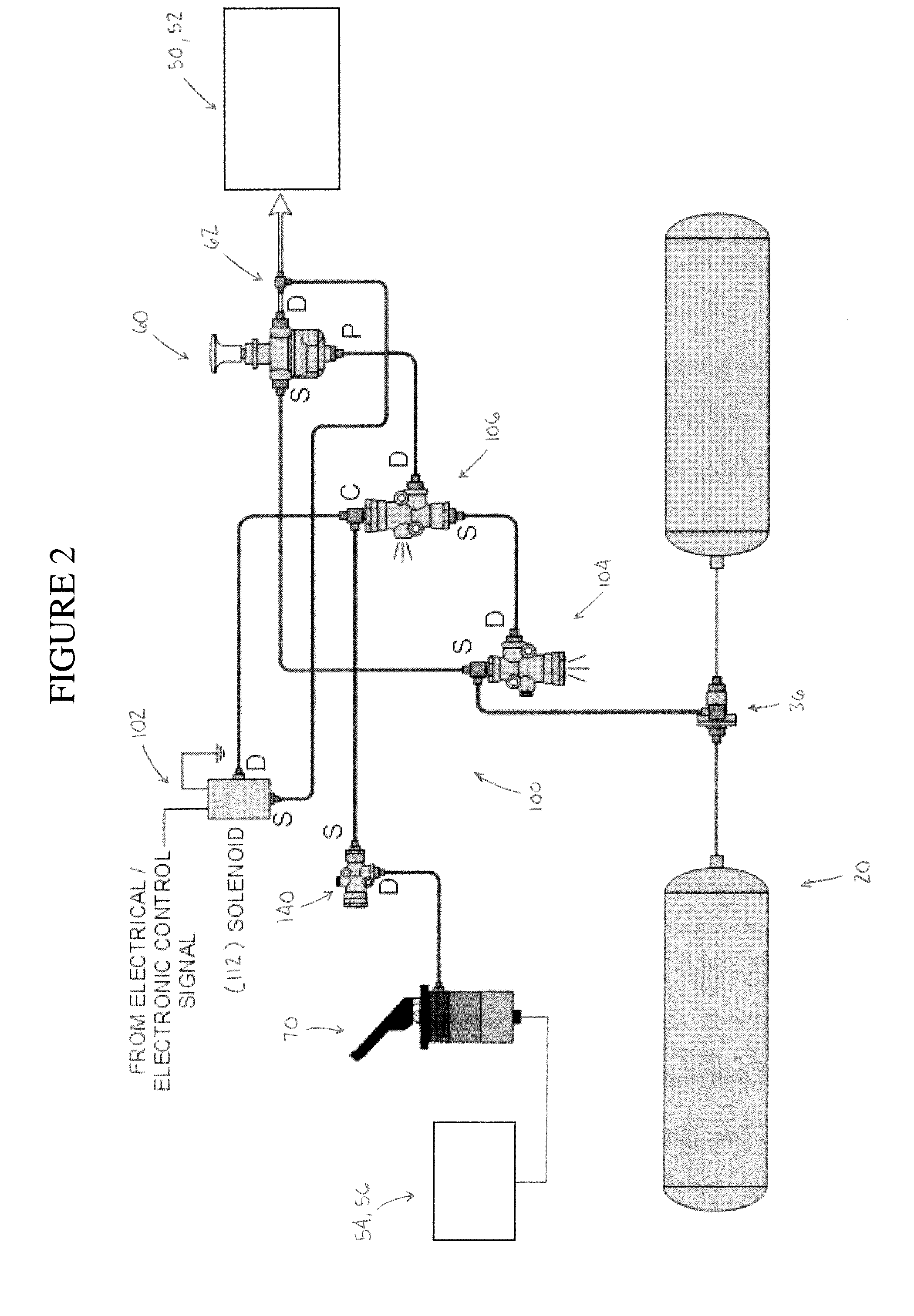
[0014]It should, of course, be understood that the description and drawings herein are merely illustrative and that various modifications and changes can be made to the pneumatic brake system or park system disclosed without departing from the scope of the present disclosure. It will also be appreciated that the various identified components of the pneumatic brake system disclosed herein are merely terms of art that may vary from one manufacturer to another and should not be deemed to limit the present disclosure. Further, details of the identified components of the pneumatic brake system disclosed herein are well known and are commercially available from the assignee of the subject invention so that only selected details will be described herein for purposes of brevity.

[0015]Referring now to the drawings wherein like numerals refer to like parts throughout the several views, FIGS. 1 and 2 partially schematically illustrate a pneumatic park system or brake system according to one as...


PUM


Abstract

A pneumatic brake system for a heavy duty vehicle is provided. The heavy duty vehicle has at least one source of pressurized air for pressurizing the brake system, at least one spring brake chamber including a spring brake assembly, and at least one service brake chamber including a service brake assembly. The brake system includes a first control valve, a second control valve and a work brake system. The first control valve is in communication with the source of pressurized air. The first control valve delivers pressurized air to the spring brake chamber and exhausts pressurized air to atmosphere to activate the spring brake assembly when brake system pressure is reduced to a predetermined low trip brake system pressure. The second control valve is in communication with the source of pressurized air and selectively delivers pressurized air to the service brake chamber for application of the service brake assembly. The work brake system is in communication with the source of pressurized air, the first control valve, and the second control valve. The work brake system is operably dependent on a predetermined high trip brake system pressure and a predetermined reset brake system pressure. Upon actuation of the work brake system, when brake system pressure is greater than the predetermined high trip pressure, the work brake system is configured to deliver a pneumatic control signal to the second control valve to activate the service brake assembly. When brake system pressure is less than the predetermined high trip pressure, the work brake system is configured to deliver a pneumatic spring brake signal to the first control valve to activate the spring brake assembly and remove the pneumatic control signal to the second control valve. The delivery of the pneumatic control signal to the second control valve via the work brake system is prevented until brake system pressure is greater than the predetermined reset pressure.

Description

BACKGROUND[0001]The present disclosure generally relates to pneumatic brake systems for heavy duty vehicles that make frequent stops in their vocation.[0002]Pneumatic or air pressure-actuated brake systems for heavy duty vehicles are well known. Such brake systems utilize pressurized air to actuate a brake assembly in a brake chamber of the vehicle. Air actuation of the brake assembly is known in the art as a service brake application and is carried out to slow down or stop the vehicle while it is in motion. In addition to service brakes, it is common for heavy duty vehicles to include spring brakes, which are activated in a parking brake application to lock the brake assemblies in a park position when the vehicle is at rest. The brake assembly is locked in the park position through the expansion force of a spring located within the brake chamber, which is kept compressed in the non-activated state through application of air pressure. Actuation of the spring brakes is effected by ve...

Claims


Application Information

Patent Timeline
IPC IPC(8): B60T8/88
CPCB60T13/662B60T17/22B60T17/02B60T13/683
Inventor RIPLEY, JOHN V.EBERLING, CHARLES E.
Owner BENDIX COMML VEHICLE SYST LLC
Features
  • Generate Ideas
  • Intellectual Property
  • Life Sciences
  • Materials
  • Tech Scout
  • Unparalleled Data Quality
  • Higher Quality Content
  • 60% Fewer Hallucinations
Learn More