
Low frequency oscillator, the omni-directional type low frequency underwater acoustic transducer using the same and the cylindrical radiation type low frequency underwater acoustic transducer using the same

a low frequency oscillator and low frequency technology, applied in the field of low frequency oscillators, can solve the problems of large mechanical size, limited production methods, and vibrators or oscillators with a small size and lowered mechanical resonance, and achieve the effects of low frequency operation, light weight and small siz

Inactive Publication Date: 2009-09-24
NEC CORP
View PDF2 Cites 17 Cited by
  • Summary
  • Abstract
  • Description
  • Claims
  • Application Information

AI Technical Summary

Benefits of technology

[0009]An exemplary object of the present invention is to provide a low frequency oscillator enabling low frequency operation with small size and light-weight, and to provide an omni-directional type low frequency underwater acoustic transducer using the above-mentioned oscillator, and a cylindrical radiation type low frequency underwater acoustic oscillator.

Problems solved by technology

Thus, in order to form a transducer for low frequency, large mechanical size is inevitably needed.
Accordingly, in the transducer for the low frequency, the miniaturization and the weight saving are always required, and the realization of a vibrator or oscillator which has a small size with lowered mechanical resonance is a technical issues.
However, in view of the strength of the whole vibrating plate, its production method is limited.
Even if the vibrating plate is used, in order to aim at further lowering its frequency, the transducer's size tends to become large and its weight is also increased, and thus causing such problems as difficulty for achieving small size and light-weight for the transducer.

Method used


Image

  • Low frequency oscillator, the omni-directional type low frequency underwater acoustic transducer using the same and the cylindrical radiation type low frequency underwater acoustic transducer using the same
  • Low frequency oscillator, the omni-directional type low frequency underwater acoustic transducer using the same and the cylindrical radiation type low frequency underwater acoustic transducer using the same
  • Low frequency oscillator, the omni-directional type low frequency underwater acoustic transducer using the same and the cylindrical radiation type low frequency underwater acoustic transducer using the same

Examples


Embodiment Construction

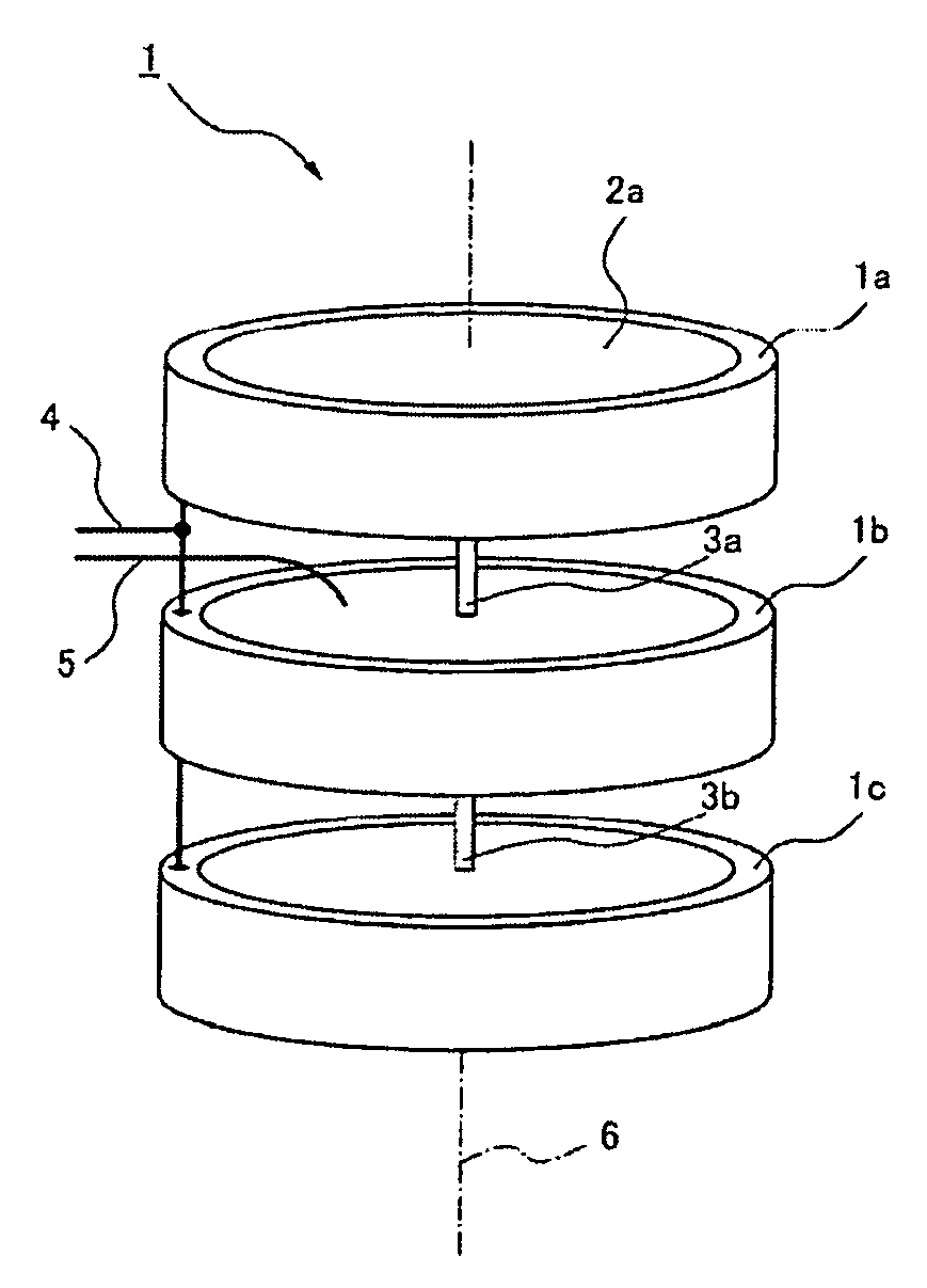
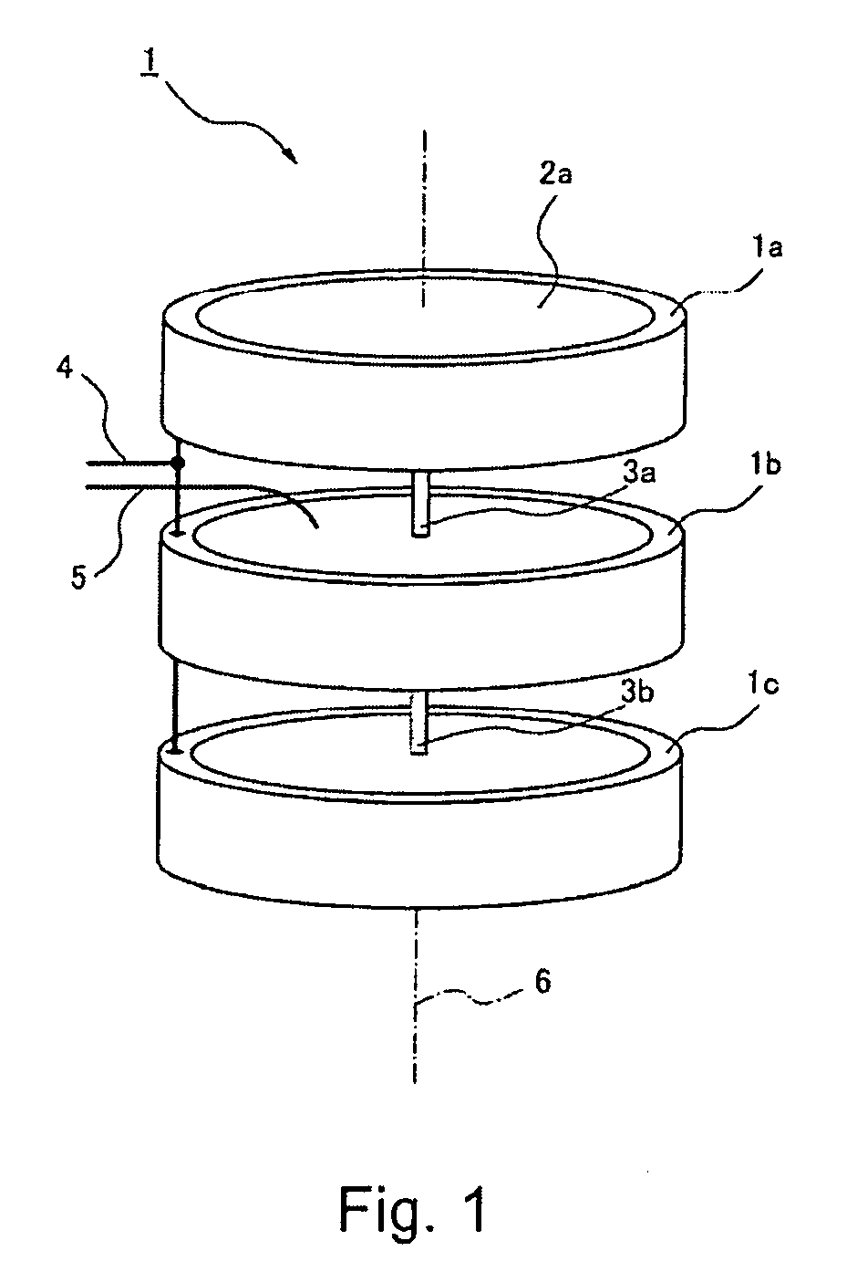
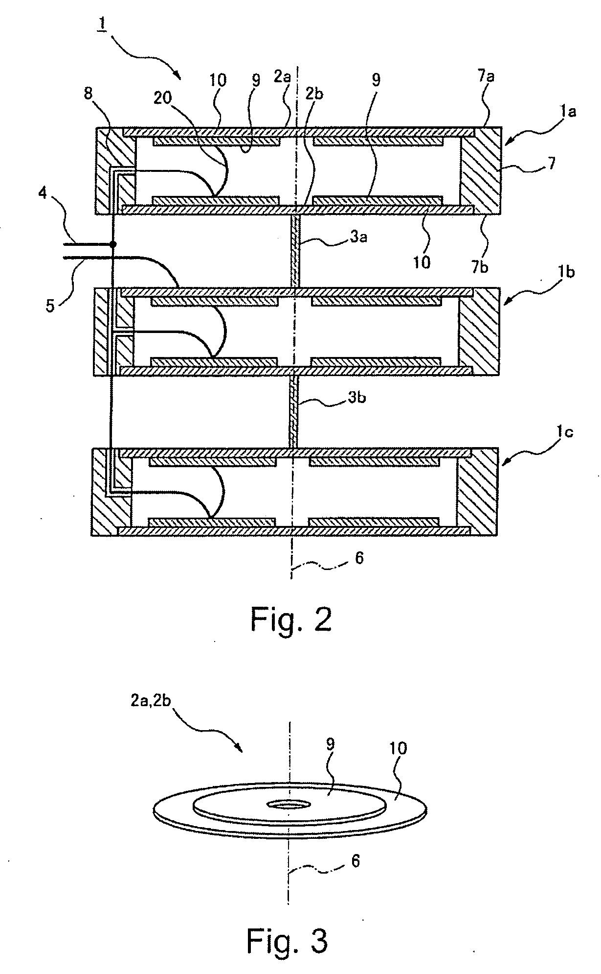
[0037]A low frequency oscillator which is an exemplary embodiment of the present invention, an omni-directional type low frequency underwater acoustic transducer (hereinafter referred to an omni-directional type transducer) using the low frequency oscillator, and a cylindrical radiation type low frequency underwater acoustic transducer (hereinafter referred to a cylindrical radiation type transducer) using the low frequency oscillator will be described in detail in the following, referring to drawings appropriately. The drawings are simply referred to describe the low frequency oscillator, the omni-directional type transducer and the cylindrical radiation type transducer of exemplary embodiments, and dimensions of each illustrated part is not identical to an actual dimensions such as thickness and size of each members.

Exemplary Embodiment of a Low Frequency Oscillator

[0038]The low frequency oscillator 1 of this exemplary embodiment will be described in detail in the following by ref...


PUM


Abstract

A low frequency oscillator includes a plurality of drum-shaped oscillators. Each of the drum-shaped oscillators is constructed so that a pair of disk-shaped flexural vibrators is attached on both open ends of a conductive cylinder so as to be arranged face to face. And a conductive elongated coupling member is fixed to adjacent the drum-shaped oscillators at a central portion thereof so as to electrically connect between adjacent the disk-shaped flexural vibrators and thereby coupling the drum-shaped oscillators along a central axis thereof.

Description

[0001]This application is based upon and claims the benefit of priority from Japanese patent application No. 2008-073604, filed on Mar. 21, 2008 and the disclosure of which is incorporated herein in its entirety by reference.1. TECHNICAL FIELD[0002]The present invention relates to a transducer of a sound wave for underwater and relates to an omni-directional type low frequency underwater acoustic transducer and a cylindrical radiation type low frequency underwater acoustic transducer using the low frequency oscillator having a disk-shaped flexural vibrator.2. BACKGROUND ART[0003]Recently, in a field of an oceanographic survey, a sound wave having low frequency is often used because of low attenuation and good propagation characteristic in water, and thus various low frequency transducers are realized for a practical use.[0004]For example, Japanese Patent Application Laid-Open No. Hei-3 (1991)-11898 (patent document 1: refer to page 3, FIG. 1 and FIG. 3) shows a transducer where a me...

Claims


Application Information

Patent Timeline
Patent Type & Authority Applications(United States)
IPC IPC(8): H01L41/09
CPCB06B1/0603
Inventor SHIBA, HIROSHI
Owner NEC CORP
Learn More