Apparatus of dynamic feedback control charge pump

a charge pump and dynamic feedback technology, applied in the direction of dc-dc conversion, power conversion systems, instruments, etc., can solve the problems of increasing the burden of cost, generating serious ripple problems, and unable to fully exert the functions of the charge pump, so as to improve the output voltage ripple and improve the output efficiency of the charge pump

Active Publication Date: 2009-09-24
NOVATEK MICROELECTRONICS CORP
View PDF5 Cites 18 Cited by
  • Summary
  • Abstract
  • Description
  • Claims
  • Application Information

AI Technical Summary

Benefits of technology

[0012]The present invention provides an apparatus of dynamic feedback control charge pump, which integrates the multiple effect of the charge pump, the voltage regulation characteristic of the voltage regulator, and the real-time detection and feedback capability of the feedback unit, for dynamically detecting and feeding back the output voltage, so as to respond to the current change caused by load in real time, thereby improving the output efficiency of the charge pump and reducing the output voltage ripple without adding additional elements and cost.

Problems solved by technology

However, in order to extend the applications of the charge pump circuit in various environments (i.e., the input voltage is uncertain when the charge pump circuit is designed), for generating the expected output voltages, usually, a voltage regulator circuit is used to first regulate the levels of the output voltage to a rated voltage, and the charge pump is then used to generate a rated output voltage.
The conventional charge pump may provide the voltage twice that of the input voltage Vin1, but when current at the output end of the charge pump changes due to the load variation, the voltage regulator circuit cannot detect and regulate the input voltage Vin1 in real time according to the change of the output current, such that the output voltage Vout1 generates a serious ripple problem along with the change of the load current.
However, this solution causes the load problem of the voltage regulator, and the added regulator capacitor also increase the burden of cost, such that the functions of the charge pump cannot be fully exerted.

Method used


Image

  • Apparatus of dynamic feedback control charge pump
  • Apparatus of dynamic feedback control charge pump
  • Apparatus of dynamic feedback control charge pump

Examples


Embodiment Construction

[0023]Reference will now be made in detail to the present embodiments of the invention, examples of which are illustrated in the accompanying drawings. Wherever possible, the same reference numbers are used in the drawings and the description to refer to the same or like parts.

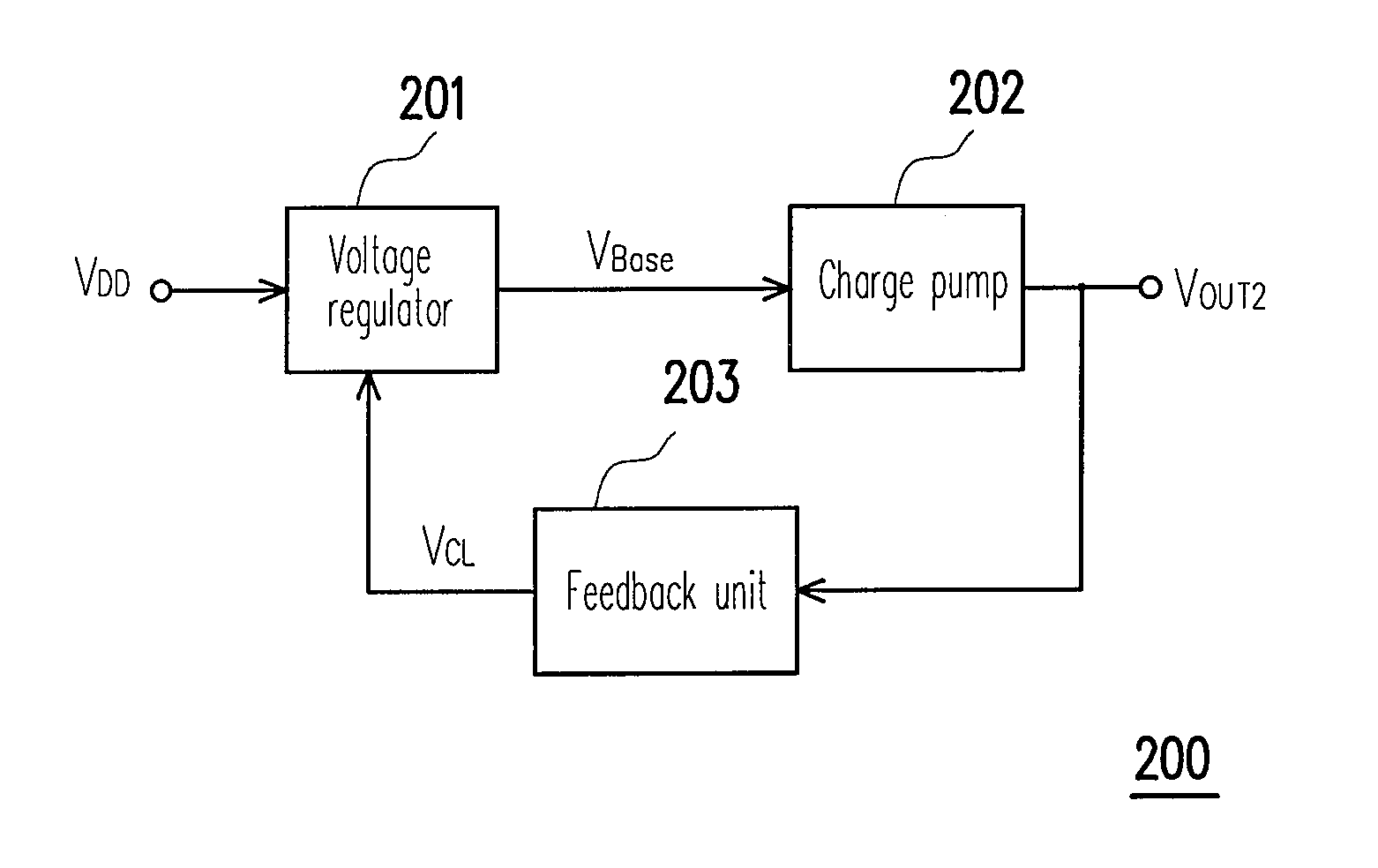
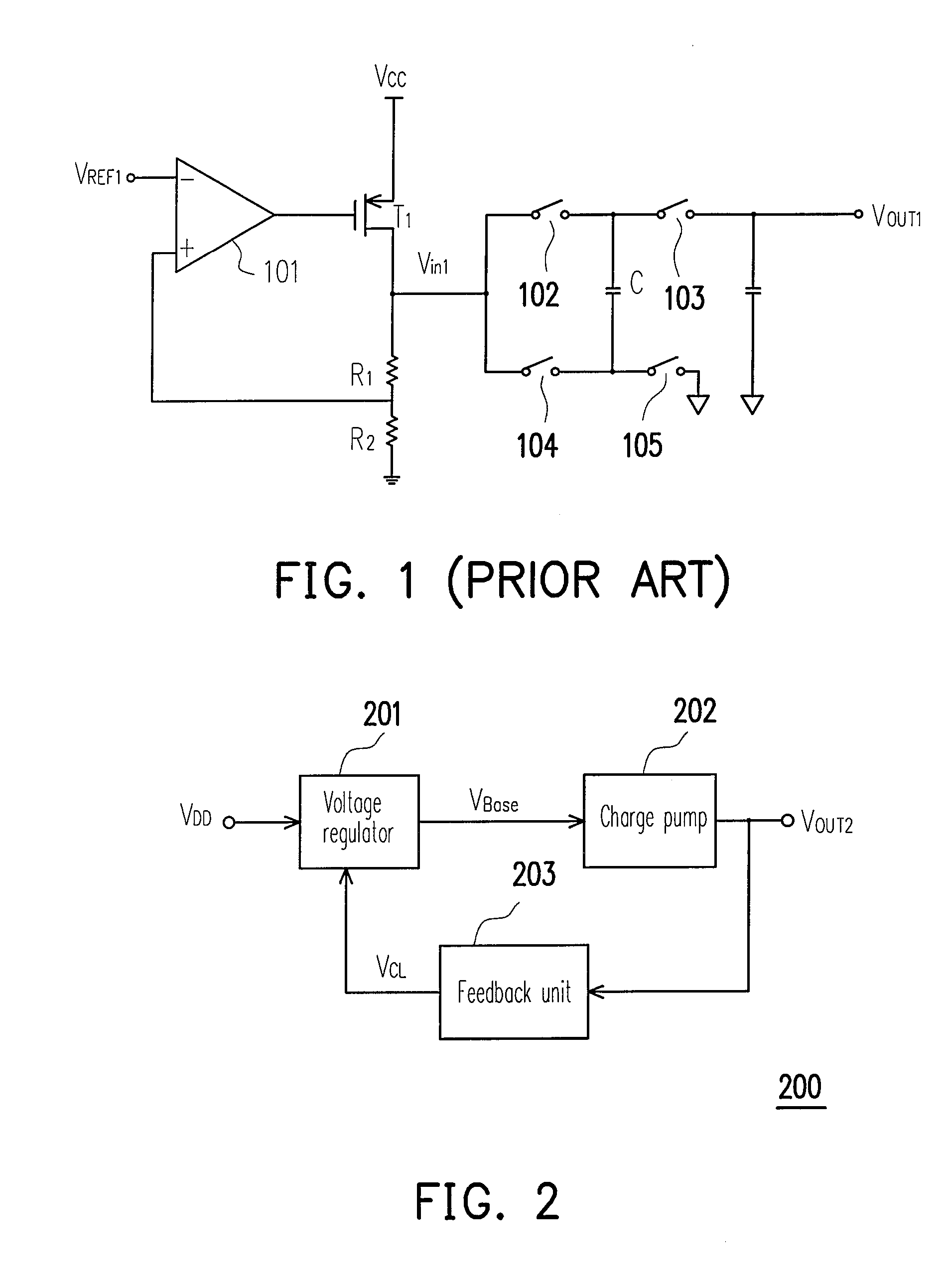
[0024]The conventional charge pump cannot respond to the change at the output end in real time. When the current at the output end changes due to the load variation, the output voltage generated by the conventional charge pump has a serious ripple problem along with the current change. Accordingly, the present invention utilizes a feedback unit having the real-time detection and feedback capability in the following embodiments to achieve the effect of improving the output efficiency of the charge pump and reducing the output voltage ripple.

[0025]FIG. 2 is a schematic view of an apparatus of dynamic feedback control charge pump 200 according to an embodiment of the present invention. Referring to FIG. 2, the ap...


PUM


Abstract

An apparatus of dynamic feedback control charge pump is provided. The apparatus of dynamic feedback control charge pump receives an input voltage through a voltage regulator. The voltage regulator regulates the input voltage to a base voltage according to a control signal. The charge pump receives the base voltage and provides multiple of the base voltage to an output voltage. A feedback unit provides the control signal to the voltage regulator according to the output voltage. Therefore, the apparatus of dynamic feedback control charge pump can reduce the output voltage ripple and improve the output efficiency of the charge pump.

Description

CROSS-REFERENCE TO RELATED APPLICATION[0001]This application claims the priority benefit of Taiwan application serial no. 97110409, filed Mar. 24, 2008. The entirety of the above-mentioned patent application is hereby incorporated by reference herein and made a part of this specification.BACKGROUND OF THE INVENTION[0002]1. Field of the Invention[0003]The present invention relates to a charge pump apparatus, in particular, to a charge pump apparatus having dynamic feedback control capability.[0004]2. Description of Related Art[0005]An electronic circuit often needs various power supply voltages of different levels, and thus a charge pump circuit is usually configured to use the existing power supply voltage to generate various power supply voltages of different levels. The charge pump circuit generates the voltages of different levels by boosting (or bucking) the input voltage with a predetermined multiple. Therefore, the levels of the output voltage of the charge pump circuit are cl...

Claims


Application Information

Patent Timeline
Patent Type & Authority Applications(United States)
IPC IPC(8): G05F1/00
CPCH02M2001/0045H02M3/07H02M1/0045
Inventor HSIEH, CHIH-YUANCHENG, LAN-SHAN
Owner NOVATEK MICROELECTRONICS CORP
Why Eureka
Try Eureka