Amplification type solid-state imaging device
- Summary
- Abstract
- Description
- Claims
- Application Information
AI Technical Summary
Benefits of technology
Problems solved by technology
Method used
Image
Examples
first embodiment
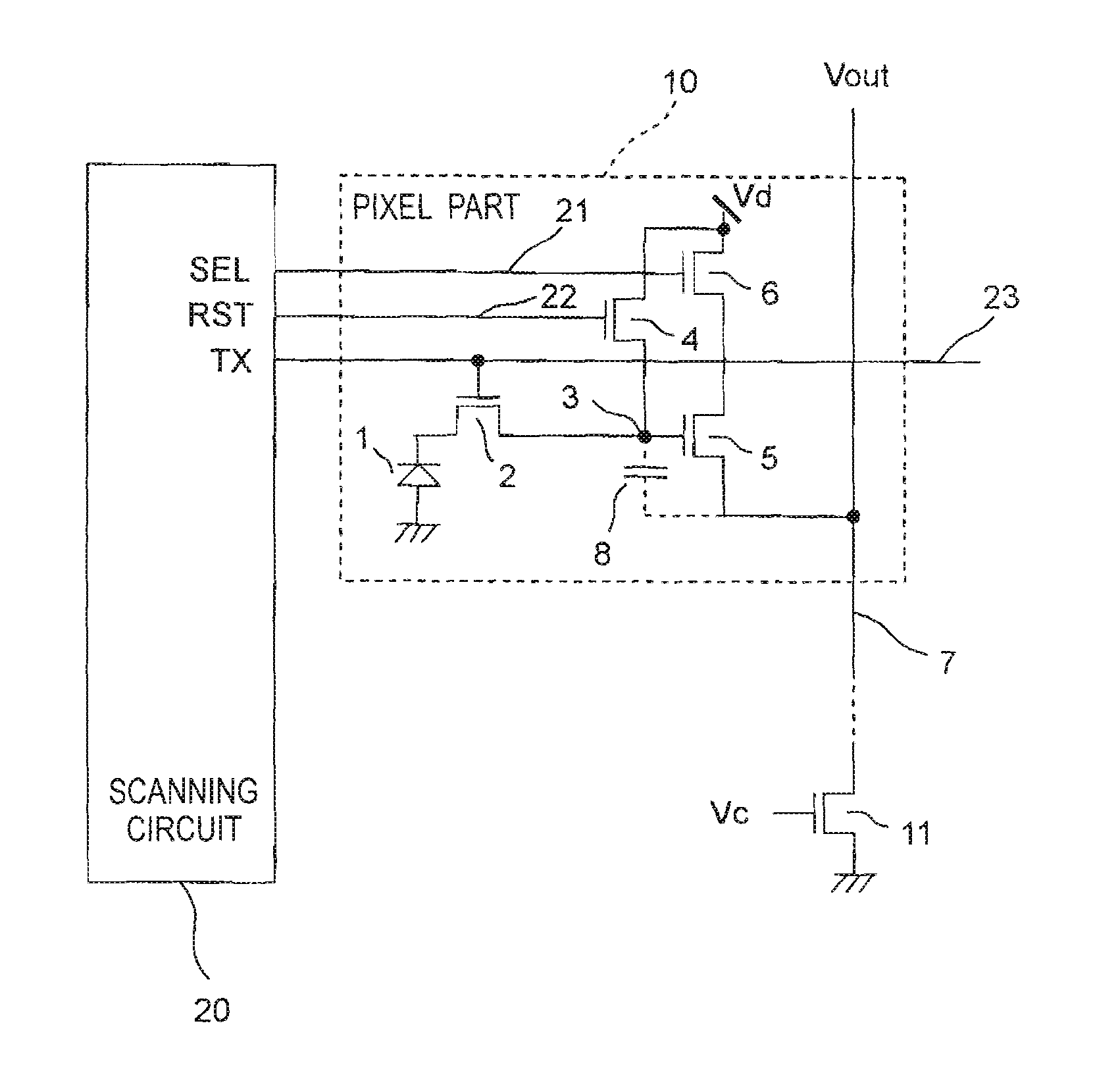
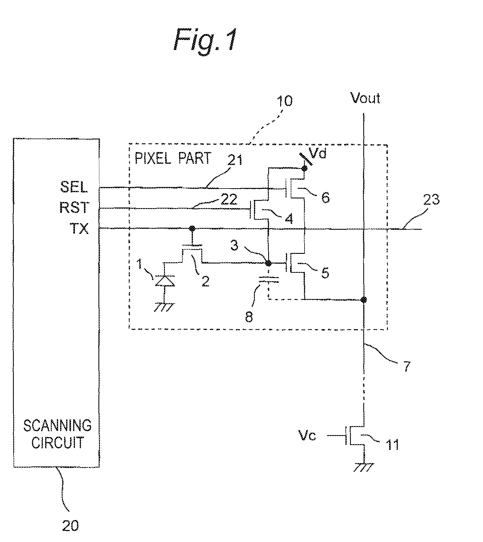
[0056]FIG. 1 is a circuit diagram showing the essential part of the amplification type solid-state imaging device of the first embodiment of the invention. The amplification type solid-state imaging device of the first embodiment has a plurality of pixel parts 10 arranged in a matrix form and a scanning circuit 20 as one example of the control section to control the pixel parts 10. In FIG. 1, only one pixel part 10 is shown. The pixel part 10 and the scanning circuit 20 are formed on a semiconductor substrate (not shown).
[0057]The pixel part 10 has an embedded type photodiode 1 as one example of the photoelectric transducer, a transfer transistor 2 that transfers a signal charge from the photodiode 1, a signal charge accumulating portion 3 that accumulates the signal charge of the photodiode 1 transferred from the transfer transistor 2, a reset transistor 4 that resets the voltage of the signal charge accumulating portion 3, an amplifying transistor 5 that amplifies and reads the vo...
second embodiment
[0079]FIG. 3 is a timing chart showing the essential part of an amplification type solid-state imaging device according to a second embodiment of the invention. In this case, the circuit diagram of the objective pixel part is the same as that of the pixel part of the amplification type solid-state imaging device of the first embodiment shown in FIG. 1.
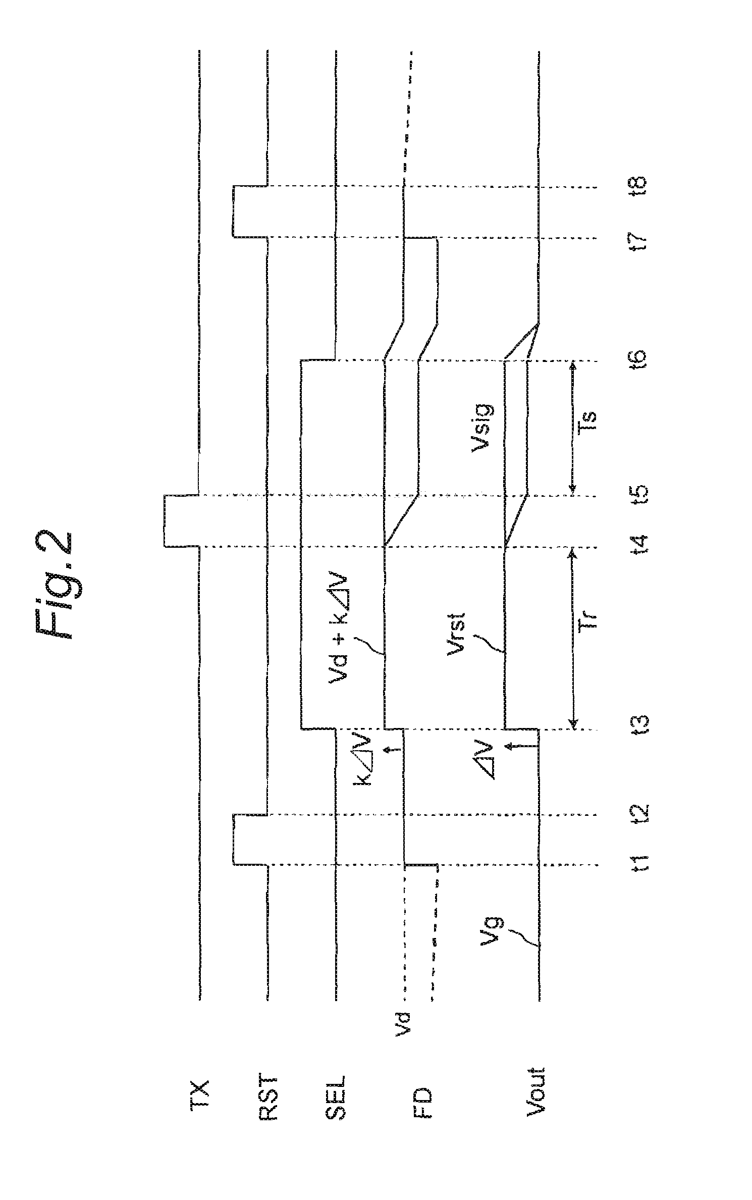
[0080]The amplification type solid-state imaging device of the second embodiment has a timing different from the timing chart shown in FIG. 2 of the first embodiment in the point that the reset signal RST is fixed to high level until time t2 and after time t7, i.e., the point that the low level is only in the period of t2 to t7. In FIG. 3, the period of t1 to t8 is that same as in FIG. 2, and therefore, the operation in the period is the same as in FIG. 2. Further, in the case of FIG. 3, the reset transistor 4 is consistently on until time t1 and after time t8 in a non-read period, and therefore, the voltage of the signal charge accumu...
third embodiment
[0081]FIG. 4 is a circuit diagram showing the essential part of an amplification type solid-state imaging device according to the third embodiment of the invention. The amplification type solid-state imaging device of the third embodiment has the same construction as that of the amplification type solid-state imaging device of the first embodiment except that the reset transistor 14 and the select transistor 16 are depletion type MOS type transistors, a switch transistor 12 is provided between the read signal line 7 and the constant current load 11 and except a scanning circuit 40.
[0082]As shown in FIG. 4, the amplification type solid-state imaging device of the third embodiment has a plurality of pixel parts 30 arranged in a matrix form and the scanning circuit 40 as one example of the control section to control the pixel parts 30. In FIG. 4, only one pixel part 30 is shown. The pixel parts 30 and the scanning circuit 40 are formed on a semiconductor substrate (not shown).
[0083]The...
PUM
 Abstract
Description
Claims
Application Information
 - R&D
- Intellectual Property
- Life Sciences
- Materials
- Tech Scout
- Unparalleled Data Quality
- Higher Quality Content
- 60% Fewer Hallucinations
Browse by: Latest US Patents, China's latest patents, Technical Efficacy Thesaurus, Application Domain, Technology Topic, Popular Technical Reports.
© 2025 PatSnap. All rights reserved.Legal|Privacy policy|Modern Slavery Act Transparency Statement|Sitemap|About US| Contact US: help@patsnap.com


