[0012]An
advantage of some aspects of the invention is that it provides a horizontal
electric field mode
liquid crystal display device capable of lowering contrast of an image when a display screen is viewed in a direction oblique to a normal direction thereof at a display mode of a narrow viewing angle by optimizing a driving
voltage of viewing-angle control pixels relative to display pixels, and an electronic apparatus having the same.
[0016]In this case, by making a voltage applied between the pair of electrodes in the viewing-angle control pixel region at the time of driving the liquid crystal layer in the viewing-angle control pixel region higher than a voltage applied between the pair of electrodes in the display pixel region, for example, brightness of when the display screen is viewed from the oblique direction to the normal direction is varied. Therefore, it is possible to lower contrast of the image viewed from the oblique direction. As a result, it is possible to make it more difficult to discriminate the image viewed from the oblique direction.
[0018]In the liquid crystal device according to this aspect of the invention, preferably, one
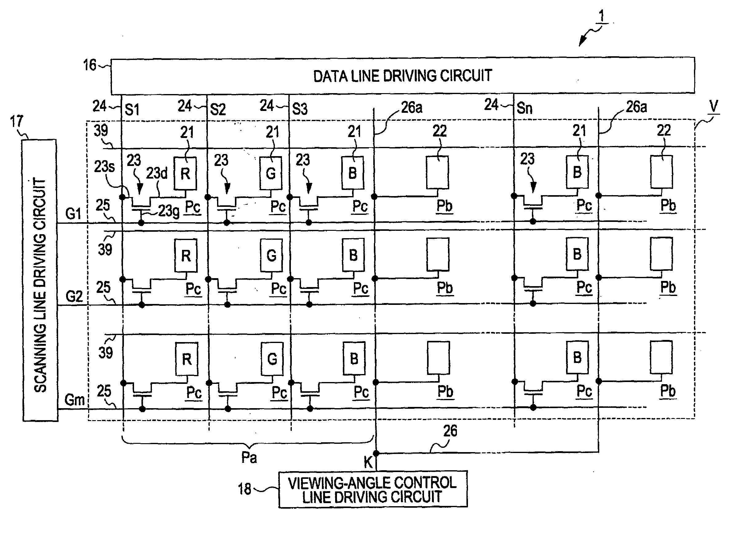
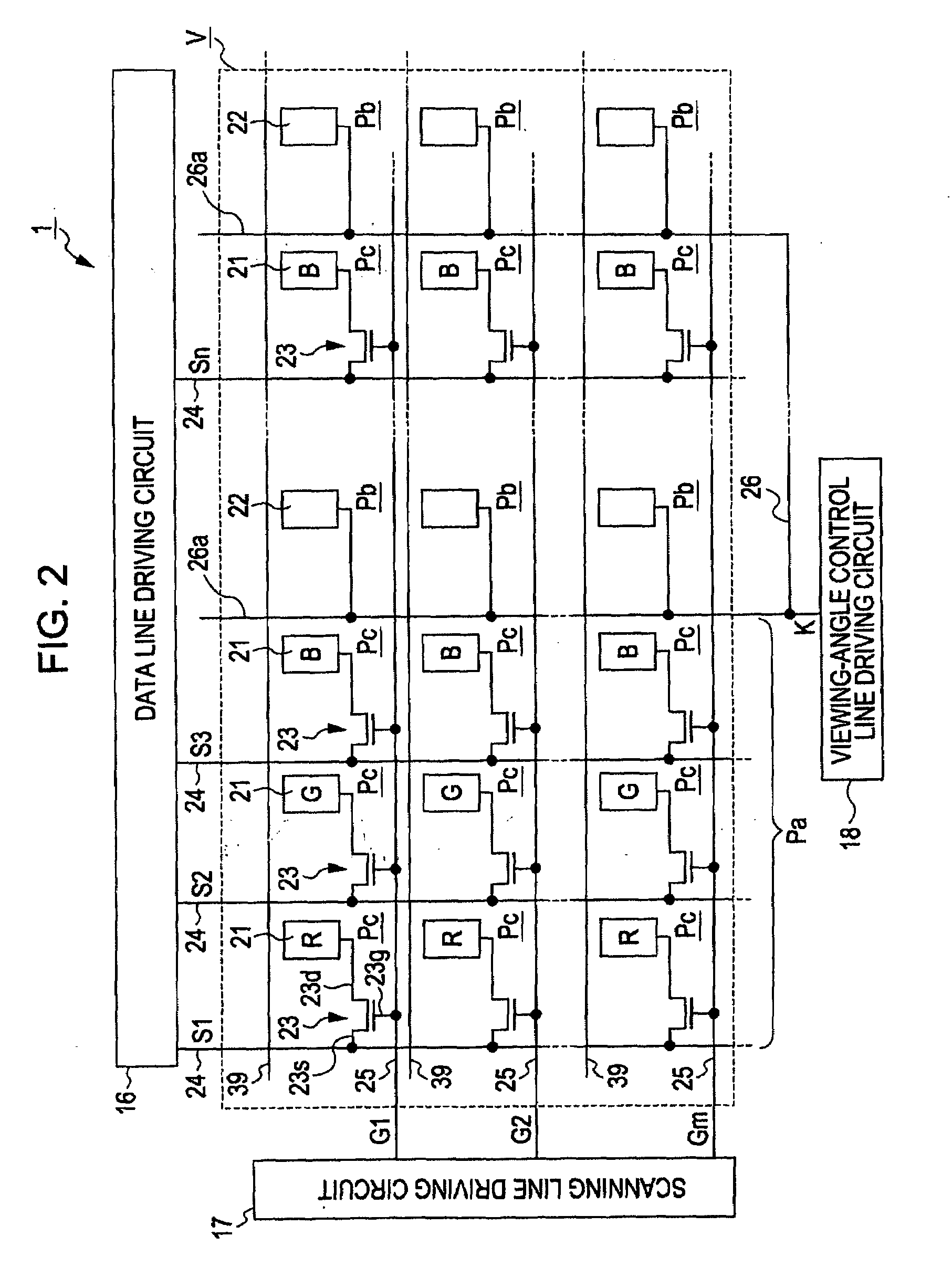
electrode of the pair of electrodes in the viewing-angle control pixel region is directly connected to a line supplied with a
control signal (for example, ON or OFF
signal). In this case, preferably, the one
electrode in the viewing-angle control pixel region is connected to a viewing-angle
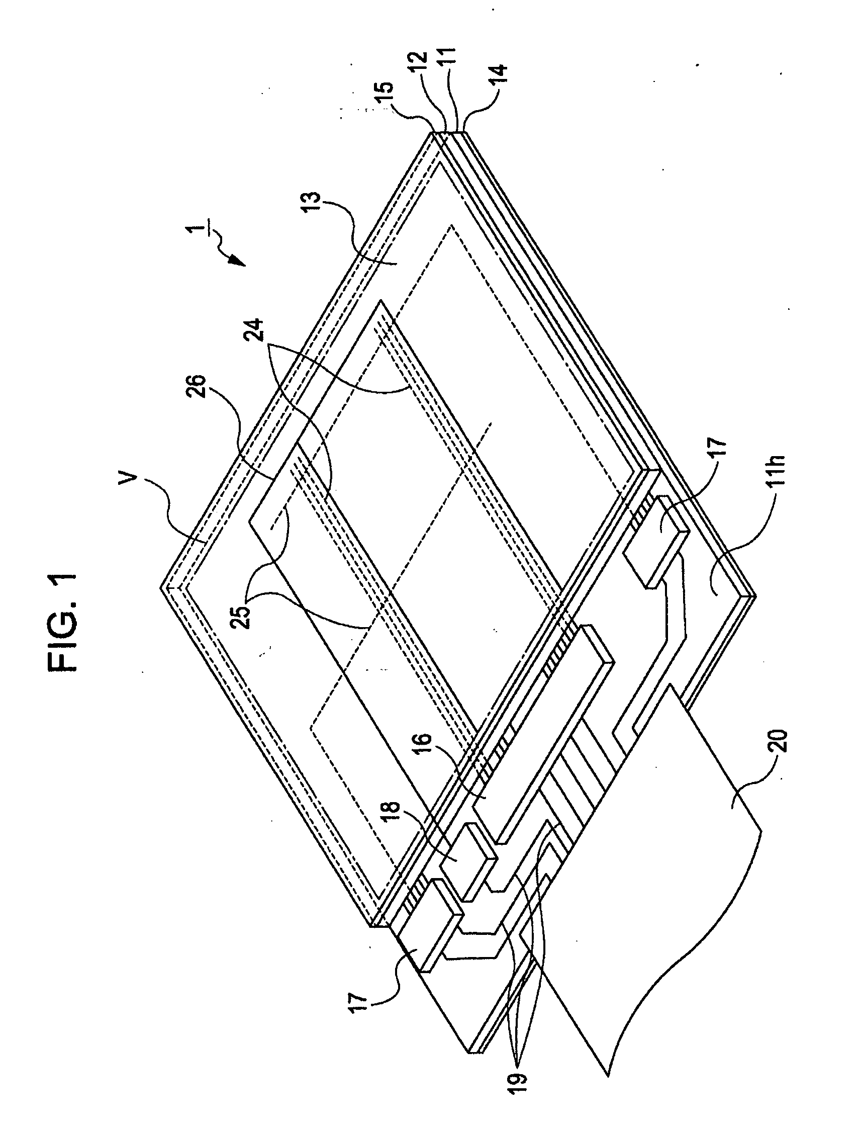
control line driving circuit through the line. The viewing-angle
control line driving circuit is configured to include a switching element such as
transistor capable of switching electric signals (ON / OFF). The viewing-angle
control line driving circuit supplies the
control signal (for example, ON or OFF
signal) to the one
electrode of the pair of electrodes in the viewing-angle control pixel region, for example, by turning the switching element ON / OFF. In addition, the circuit supplies a
signal corresponding toga predetermined reference
electric potential to the other electrode in the viewing-angle control pixel region. By adopting such a configuration, it is possible to easily and efficiently apply a
high voltage (viewing-angle
control signal) to the one electrode in the viewing-angle control pixel region without applying a load to a driver IC for driving the liquid crystal layer and the like. As a result, the narrow viewing-angle display mode can be realized without difficulty by supplying one electrode in the viewing-angle control pixel region with a
high voltage, for example, the control signal (ON signal) corresponding to the range of 10 to 15V.
[0020]By adopting such a configuration, for example, the viewing-angle control line driving circuit is capable of supplying an ON signal to an arbitrary viewing-angle control pixel region among a plurality of viewing-angle control pixel regions and simultaneously capable of supplying an OFF signal to another viewing-angle control pixel region different from the arbitrary viewing-angle control pixel region. Accordingly, by dividing a display screen (the planar region) into a plurality of display region (for example, two display regions), different viewing-angle controls (that is, narrow viewing-angle control and wide viewing-angle control) are performed on the divided display regions, respectively. For example, by applying the liquid crystal device having the configuration to a display apparatus such as a
navigation system mounted on a vehicle, a map for guiding a user's destination and the like and an image (TV program, movie, or the like) different from the map can be displayed on the display screen (dual picture display). In this case, the viewing-angle control pixels for the display region on which the map is displayed is supplied with a control signal as an OFF signal from the viewing-angle control line driving circuit through the line, and simultaneously the viewing-angle control pixels for the display region on which the image different from the map is displayed is supplied with a control signal as an ON signal from the viewing-angle control line driving circuit through the line. By adopting such a configuration, only the map can be allowed to be visible for a driver sitting on a driver's seat which is positioned obliquely to a display screen such as a
navigation system, and thus it is possible to secure
driving safety. On the other hand, both of the map and the image may be allowed to be visible for a passenger sitting on the back seat, which is positioned in front of the display screen such as the
navigation system.
[0024]By adopting such a configuration, it is possible to effectively lower contrast of the image as the display screen is viewed form the oblique direction to the normal direction when
transmittance or brightness of the image formed by the plurality of display pixel regions is high.
[0025]According to another aspect of the invention, an electronic apparatus can be configured to include the above-mentioned liquid crystal device as a display unit. By adopting such a configuration, for example, it is possible to realize an electronic apparatus that has both wide viewing-angle and narrow viewing-angle display
modes and is capable of lowering
image contrast as the display screen is viewed from the oblique direction to the normal direction at the narrow viewing-angle display mode.


