Ultra low-power transmission system

a transmission system and low-power technology, applied in the field of wireless systems, can solve the problems of increasing the latency of the operation of the wireless device, the receiver portion of the wireless device cannot receive an incoming message, and all conventional power management techniques suffer some type of drawbacks, etc., to achieve the effect of narrowing the spectrum and constant power envelop

Inactive Publication Date: 2009-09-24
TEXTRON SYST
View PDF12 Cites 15 Cited by
  • Summary
  • Abstract
  • Description
  • Claims
  • Application Information

AI Technical Summary

Benefits of technology

[0013]It is another primary object of the present invention to provide a wireless communication system comprising: 1) a transmitter for transmitting to a plurality of ultra low-power receivers a modulated downlink signal having a constant power envelope and relatively narrow spectrum; and 2) the plurality of ultra low-power receivers for receiving the modulated downlink signal. Each of the ultra low-power receivers comprises a radio frequency (RF) front-end block for receiving and demodulating the modulated downlink signal, wherein the RF front-end block includes: i) an amplifier for amplifying the received modulated downlink signal, the amplifier comprising a first plurality of enhancement mode, high-mobility electron transistors; and ii) a frequency discriminator for demodulating the amplified modulated downlink signal to thereby produce a baseband signal, the frequency discriminator comprising a second plurality of enhancement mode, high-mobility electron transistors. Each of the ultra low-power receivers further comprises a correlator for receiving the baseband signal from the frequency discriminator and detecting a codeword therein.

Problems solved by technology

However, all of the conventional power management techniques suffer some type of drawback.
However, during the dormant state, the deactivated receiver portion of the wireless device cannot receive an incoming message.
Thus, duty cycling results in increased latency in the operation of the wireless device.
However, while this gives the RFID device an extremely long lifespan, the reader device must be relatively close to the RFID device in order for it to operate.
This severely limits the operating range of an RFID device.

Method used


Image

  • Ultra low-power transmission system
  • Ultra low-power transmission system
  • Ultra low-power transmission system

Examples


Embodiment Construction

[0020]FIGS. 1 through 4, discussed below, and the various embodiments used to describe the principles of the present disclosure in this patent document are by way of illustration only and should not be construed in any way to limit the scope of the disclosure. Those skilled in the art will understand that the principles of the present disclosure may be implemented in any suitably arranged wireless receiver.

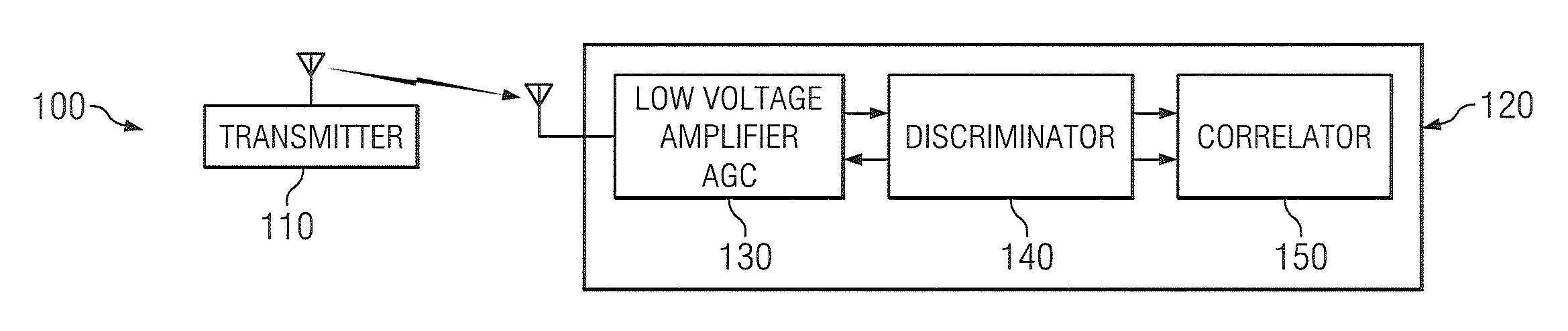
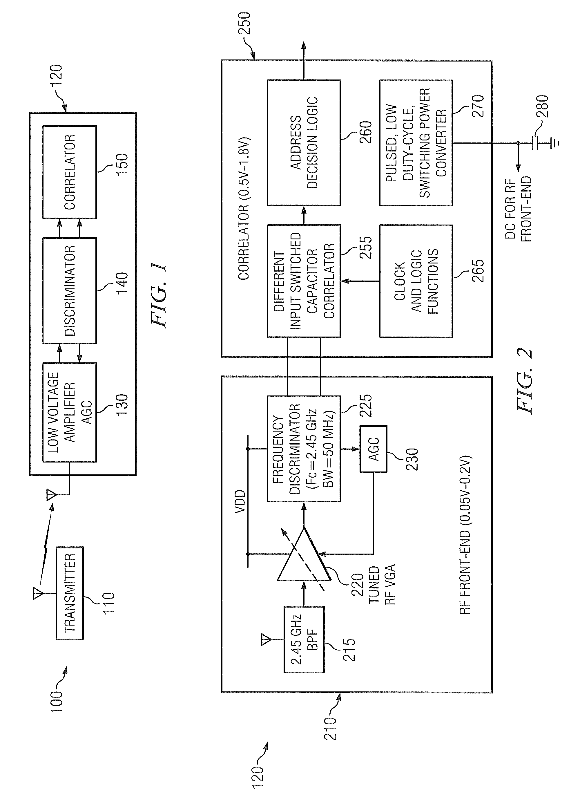
[0021]The present disclosure is directed to a wireless receiver that exhibits a long operational life, high-sensitivity reception, low response latency, and tolerance to interference. The ultra low-power receiver exhibits long operational life, since it may be left on continuously on for a period of years using only a small coin-cell or AA battery. The ultra low-power receiver is highly sensitive because an active (not passive) radio frequency (RF) front-end is used, including a low-noise amplifier (LNA) that provides the receiver with good noise figure. The ultra low-power receiv...


PUM


Abstract

An ultra low-power transmission system for use with a battery-operated device. The ultra-low power transmission system comprises an encoded transmitter and an addressable ultra -low power receiver. The ultra low-power receiver comprises an RF front-end block for receiving and demodulating an incoming RF signal. The RF front-end block includes an amplifier for amplifying the received RF signal and a frequency discriminator for demodulating the amplified RF signal to produce a baseband signal. The amplifier and the frequency discriminator are each comprised of enhancement mode, high-mobility electron transistors (E-HEMTs). The ultra low-power further receiver comprises a correlator for receiving the baseband signal from the frequency discriminator and detecting a codeword therein. The correlator comprises a plurality of switched capacitors for storing samples of the baseband signal. The correlator is operable to couple the plurality of switched capacitors in order to integrate the samples stored thereon.

Description

TECHNICAL FIELD OF THE INVENTION[0001]The present application relates generally to wireless systems and, more specifically, to an ultra low-power receiver for use in a battery-powered system with long operational life.BACKGROUND OF THE INVENTION[0002]Battery-powered wireless devices are used in a wide variety of applications. These applications include common commercial devices, such as cell phones, PDAs, hand-held GPS location devices, and the like. These applications also include more exotic applications, such as military reconnaissance or surveillance devices (e.g., microsensors) and equipment or personnel tagging (tracking) devices.[0003]A fundamental design objective in all of these applications is maximizing the battery lifespan by reducing power consumption. Many power management techniques are known in the prior art for reducing power consumption to thereby extend the operating lifespan of the battery. However, all of the conventional power management techniques suffer some ...

Claims


Application Information

Patent Timeline
Patent Type & Authority Applications(United States)
IPC IPC(8): H03D3/00H04L27/14
CPCH04L27/144H03D3/007H03K9/00H03K9/06
Inventor WEINER, DOUGLAS B.EDEN, RICHARD C.
Owner TEXTRON SYST
Why Eureka
Try Eureka