Radiotherapeutic apparatus

a radiotherapy and apparatus technology, applied in the field of radiotherapy apparatus, can solve the problems of direct correlation and limitation of the clinical effectiveness of the device, and achieve the effects of reducing the uncertainty of the isocentre location, less volume, and aggressive treatment of the tumour

Active Publication Date: 2009-09-24
ELEKTA AB
View PDF19 Cites 17 Cited by
  • Summary
  • Abstract
  • Description
  • Claims
  • Application Information

AI Technical Summary

Benefits of technology

[0015]Given that the isocentre is not actually a volume but is in fact a moving spot, the ability to calibrate the isocentre and the PSS together dynamically means both that this movement can be detected and that we can use the existing sub-millimetre accuracy of a modern PSS to compensate for isocentre movement. Thus, as the isocentre moves, the patient could be moved so as to track the moving isocentre. Even in a well-designed system with little isocentre movement, this will reduce the uncertainty in the isocentre lo

Problems solved by technology

There are a number of problems in this approach.
One such problem is that the correlation is not direct, i.e. the total error in determining the reference frame position and the isocentre will also include the error in aligning the lasers to the believed spatial location of the isocentre and the error in that spa

Method used


Image

  • Radiotherapeutic apparatus
  • Radiotherapeutic apparatus
  • Radiotherapeutic apparatus

Examples


Embodiment Construction

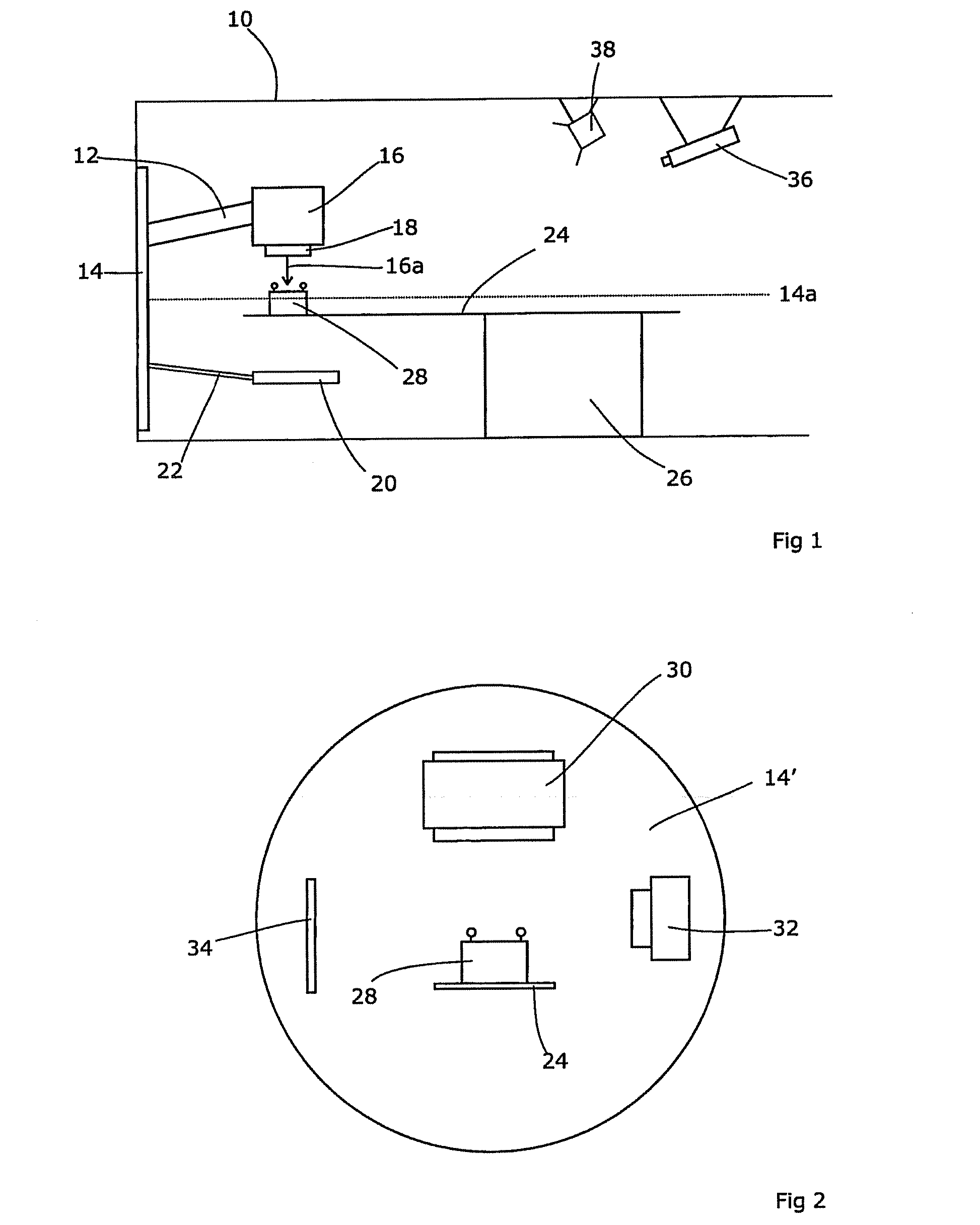
[0021]FIG. 1 shows a typical radiotherapy apparatus. A dedicated room 10 is fitted with a linear accelerator arm 12 which extends from a rotateable support 14 and ends with an x-ray head 16 for the production of therapeutic and / or diagnostic radiation. In this example, the x-ray head is adapted to produce radiation of a range of energies varying from kV energies suitable for diagnostic purposes to MV energies suitable for therapeutic use. This has the advantage that the two sources are inherently aligned in that they emanate from the same apparatus. A collimator set 18 is provided in order to shape the beam as required and contains aperture collimators, block collimators and multi-leaf collimators.

[0022]A flat panel imager 20 is provided, located on an extendable arm 22 attached to the rotateable support 14 at a location opposite the linear accelerator arm 12, i.e. spaced 180° therefrom. When the head 16 is producing low energy radiation, the imager 20 can detect the resulting image...


PUM


Abstract

A reference phantom includes CT-imageable detail together with light-reflective spheres. This item can be placed on a patient table in a known location, following which the diagnostic source can be activated to detect the phantom position relative to the isocentre and camera employed to detect the PSS position. A synthetic image of the phantom can be used for comparison with the CT dataset. This allows improved correlation of the source and the patient support, enable further steps to be taken in enhancing the clinical effectiveness of the apparatus. In-use variations of the isocentre location can be corrected in real time by adjustment of the patient support. Thus, as the isocentre moves, the patient can be moved so as to track the moving isocentre. The linac arm could also be designed differently, as the existing design constraint (that isocentre movement must be limited as far as possible) could potentially be relaxed in order to achieve other aims.

Description

CROSS-REFERENCE TO RELATED APPLICATION[0001]This Application is a Section 371 National Stage Application of International Application No. PCT / EP2007 / 001618, filed Feb. 26, 2007 and published as WO 2007 / 098899A2 and WO 2007 / 098899 A3 on Sep. 7, 2007, the content of which is hereby incorporated by reference in its entirety.FIELD OF THE INVENTION[0002]The present invention relates to radiotherapeutic apparatus.BACKGROUND ART[0003]In general, radiotherapy treatment systems involve a source of ionising radiation, such as a linear accelerator, and a patient support system (PSS) on which the patient can be placed, in the field of view of the source.[0004]The source is rotateable around the PSS so that a radiation dose can be applied to the patient from a number of directions in order to minimise the dose applied to healthy tissue, and the intersection of the axis of rotation with the beam centreline defines the “isocentre”. The PSS is moveable so as to assist in aligning the patient with t...

Claims


Application Information

Patent Timeline
IPC IPC(8): A61N5/10G01D18/00
CPCA61B6/583A61N5/1049A61N2005/1061A61N2005/1059A61N5/107A61N2005/1076A61B6/08
Inventor LONG, ANDREWVOGELE, MICHAEL
Owner ELEKTA AB
Why Eureka
Try Eureka