Motion Preserving Artificial Intervertebral Disc Device

a technology of intervertebral discs and implants, which is applied in the field of motion preservation artificial implants, can solve the problems of further complications, pain, and patient discomfort, and achieve the effects of preventing the patient from slipping, promoting self-centering, and keeping the facet joints

Inactive Publication Date: 2009-09-24
PIONEER SURGICAL TECH INC
View PDF54 Cites 86 Cited by
  • Summary
  • Abstract
  • Description
  • Claims
  • Application Information

AI Technical Summary

Benefits of technology

[0017]In this configuration, the implant more clearly mimics the natural dynamics of a natural disc joint, by allowing the upper and lower implant bodies to pivot polyaxially, as well as translate with respect to each other. The articulation interface promotes self-centering due to the mating interaction between the concave and convex articulating surfaces, which advantageously keeps the implant bodies from becoming staggered or out of alignment. The implant also helps to keep the facet joints from being unnaturally loaded when the joint is in extension. In addition, wearing of the implant is reduced, because the articulation interface is smaller than that of an articulating interface having completely matching articulating surfaces. Reduced wear increases implant lifespan and reliability, and reduces complications caused by loose wear particles in and around the implantation site.
[0018]In another form of the invention, an intervertebral implant according to the present invention provides for improved load-bearing strength, ease of insertion, and securing strength via improved securing members. The securing members may have a leading end that is beveled or contoured in the insertion direction to ease insertion of the implant. In one form, the end of the rotary shaft of the securing member is beveled to keep the securing member from binding on an adjacent bone or surrounding tissue during insertion thereof. In addition, the leading retaining member, which is in mating engagement with the securing member, may similarly be beveled or contoured to ease insertion of the implant. With this configuration, the securing member and the retaining member are operable to distract the adjacent vertebra during insertion, rather than binding or digging into the adjacent bone or tissue.
[0019]The bone-engaging members of the securing members are preferably sized and configured to increase securing strength while allowing for sufficient material thickness of the implant body to maintain sufficient load-bearing strength. In particular, the bone-engaging members are large enough to provide sufficient contact area with the adjacent bone when the securing members are deployed. In addition, the securing members are preferably disposed on portions of the implant having increased axial thickness, such that the bone-engaging members may advantageously be disposed at least partially within the implant. Further, the bone-engaging members are sized to fit at least partially within the body of the bearing member when in the undeployed configuration without compromising the structural integrity of the implant. In one preferred form, the bone-engaging members of a single securing member may have varying sizes. In addition, the bone-engaging members of one securing member disposed on the implant may be of different size than the bone-engaging members of another securing member. In one form, two securing members are disposed on the upper bearing member and one securing member is disposed on the lower bearing member. The bone-engaging members of the lower securing member are larger compared to those of the upper for increased securing strength and to compensate for having only one securing member on the lower bearing member.

Problems solved by technology

Abrupt stops in movement of the implant can be uncomfortable, painful, or even dangerous for the patient.
Further, such stops can damage the implant, causing further complications for the patient.

Method used


Image

  • Motion Preserving Artificial Intervertebral Disc Device
  • Motion Preserving Artificial Intervertebral Disc Device
  • Motion Preserving Artificial Intervertebral Disc Device

Examples


Embodiment Construction

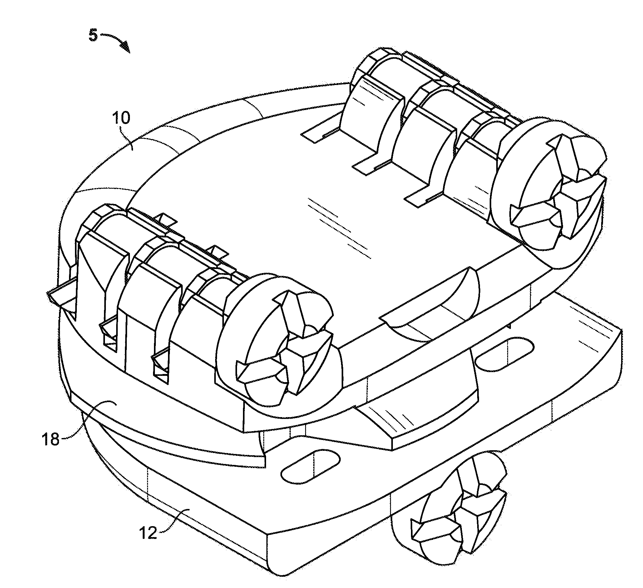
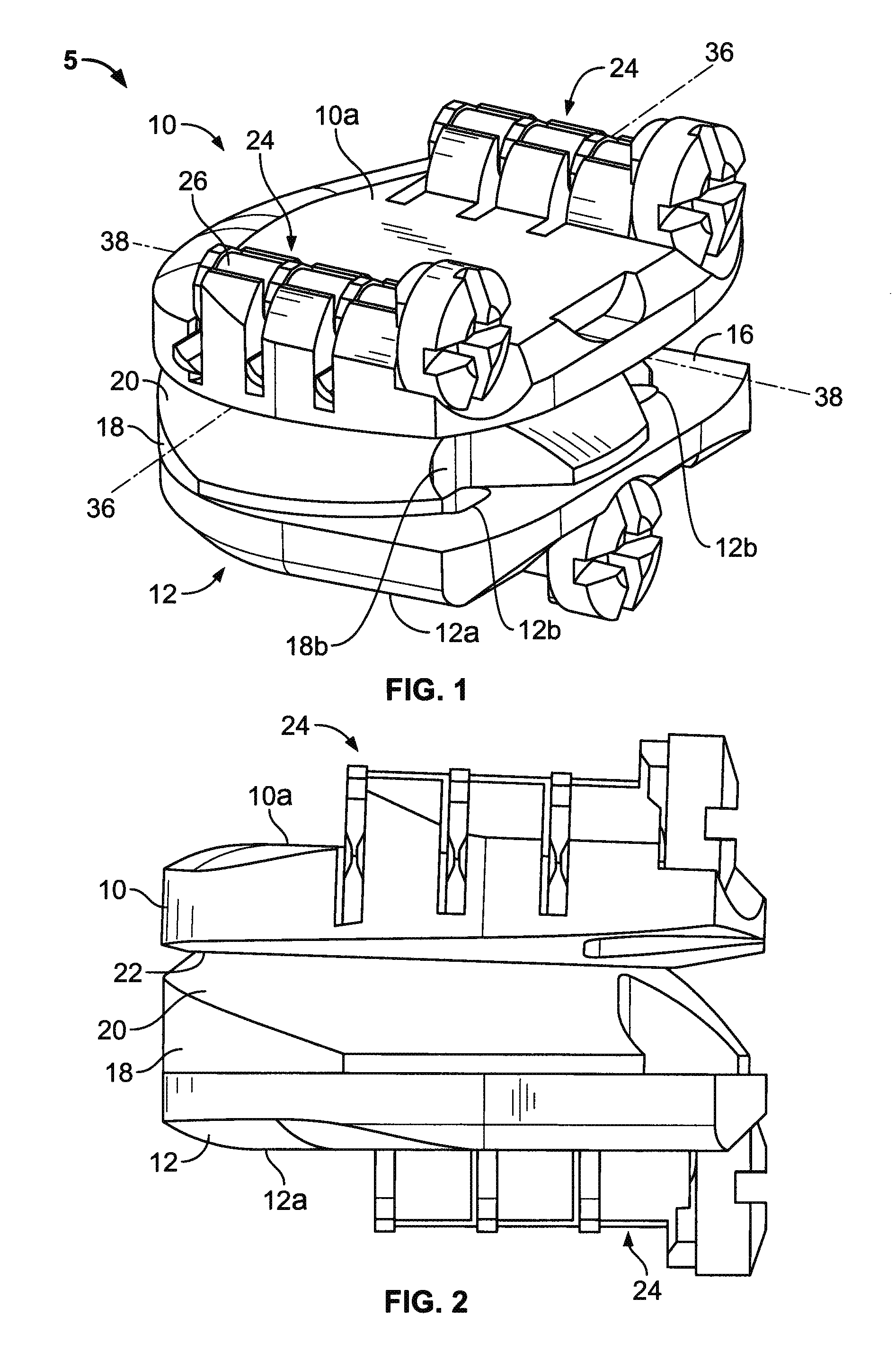
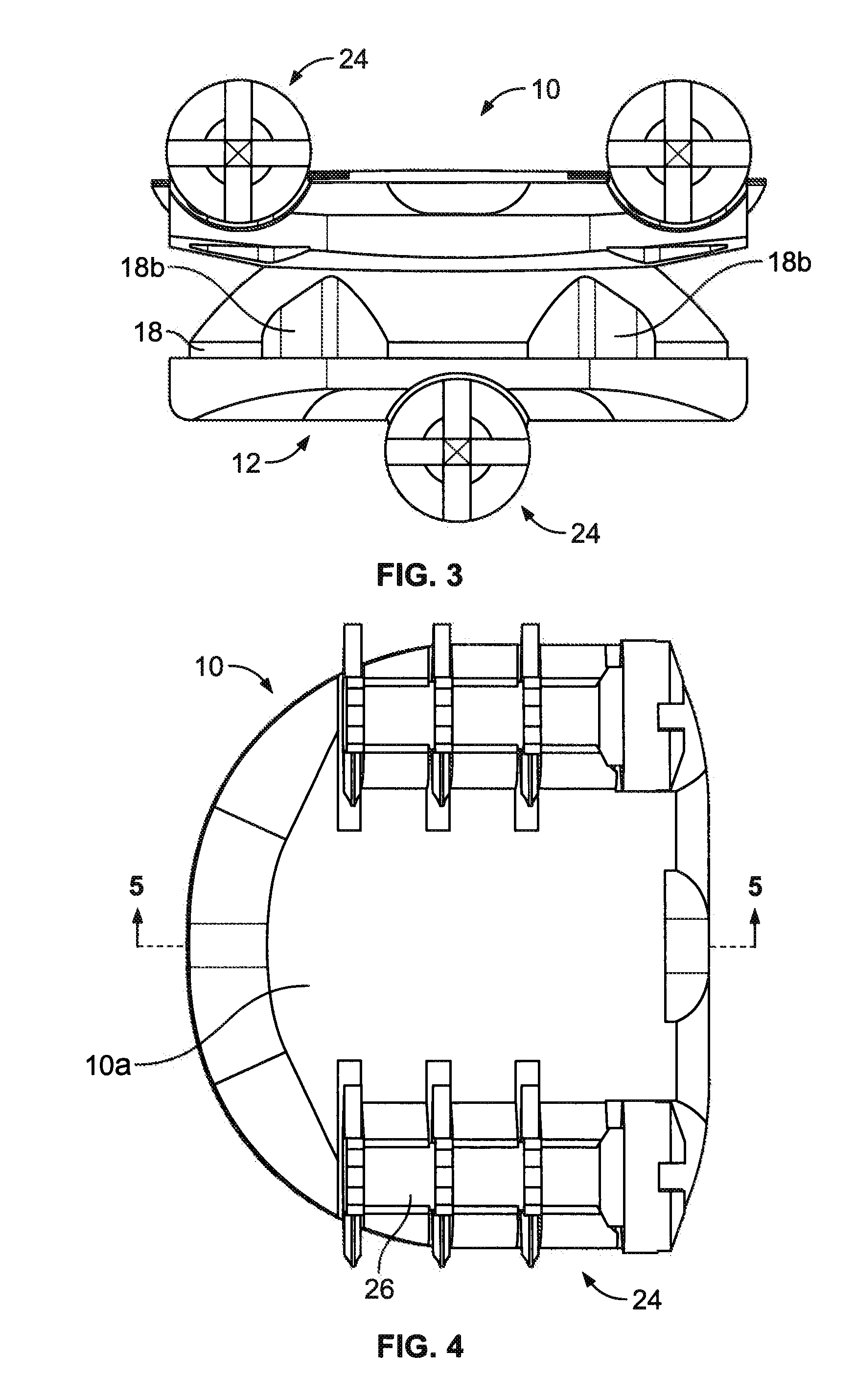
[0046]In a preferred embodiment, such as illustrated in FIGS. 1-16, an artificial disc device 5 comprises an upper implant body 10 and lower implant body 12. The upper body 10 comprises a substantially concave recess portion 14, as shown in FIG. 8, and the lower body 12 comprises a substantially flat interior portion 16, which extends generally in a transverse plane with respect to the patient as shown in FIG. 1, which may be defined by lateral axis 36 and anterior-posterior axis 38. A moveable member, such as a translatable member 18 is preferably provided between the upper and lower implant bodies 10, 12 to allow lateral movement between the bodies. Preferably, the translatable member may translate along the anterior-posterior axis 38, with the anterior side being illustrated on the right side of the page of FIG. 1 as it is implanted in the patient. The translatable member 18 may have a convex portion 20 disposed between the upper and lower implant bodies 10, 12 for providing an a...


PUM

PropertyMeasurementUnit
lengthaaaaaaaaaa
radii of curvatureaaaaaaaaaa
radius of curvatureaaaaaaaaaa

Abstract

A motion preserving implant having first and second bearing members and a biasing member disposed therebetween operable to provide resistance to the translation of the bodies with respect to one another. An intervertebral implant having first and second bearing members, a translatable member, a resilient connection between the translatable member and one of the bearing members to allow for relative motion therebetween and bearing surfaces of the translatable member and the other bearing member to allow complex, natural motion between the bearing members. A spinal implant having upper and lower bodies and an articulation surface that allows for polyaxial articulation and translation through a concave articulation surface having a first radius of curvature and a second radius of curvature in at least one plane, and a convex articulation surface having the first radius of curvature in the same plane.

Description

RELATED APPLICATIONS[0001]This application is a continuation-in-part of U.S. patent application Ser. No. 11 / 856,667, filed Sep. 17, 2007, and claims the benefit of U.S. Provisional Patent Application No. 61 / 050,612, filed May 5, 2008, both of which are incorporated herein by reference in their entirety.FIELD OF THE INVENTION[0002]The invention relates to motion preserving artificial implants for weight bearing joints, and, more particularly, to motion preserving artificial intervertebral disc implants having components that include an articulating interface therebetween.BACKGROUND OF THE INVENTION[0003]Joint degeneration is a common problem that can occur in a variety of joints throughout the human body. The condition typically is more prevalent as the skeletal system ages and is often treated with medications and / or physical therapy. These conservative treatments sometimes meet only limited success. If unsuccessful, the patient typically will continue to experience ongoing pain and...

Claims


Application Information

Patent Timeline
Patent Type & Authority Applications(United States)
IPC IPC(8): A61F2/44
CPCA61B17/86A61F2/44A61F2/4425A61F2/4611A61F2/4684A61F2002/30112A61F2002/30383A61F2002/30387A61F2002/305A61F2002/30571A61F2002/30578A61F2002/30579A61F2002/30601A61F2002/30662A61F2002/30823A61F2002/30884A61F2002/30894A61F2002/30899A61F2002/30904A61F2002/449A61F2002/4627A61F2002/4628A61F2220/0025A61F2230/0004A61F2310/00796
Inventor TRUDEAU, JEFFREY L.BAO, QI-BINJANOWSKI, BRIANPERNSTEINER, WESTONBROWN, TIM
Owner PIONEER SURGICAL TECH INC
Why Eureka
Try Eureka