Abrasive Dental Floss and Method of Making Same

a technology of dental floss and abrasive coating, which is applied in the field of dental floss, can solve the problems of difficult grasping of dental floss by users, and achieve the effects of facilitating the cleaning of dental interstices, uniform width and thickness, and enhancing grip

Inactive Publication Date: 2009-10-01
COLTEC IND
View PDF11 Cites 16 Cited by
  • Summary
  • Abstract
  • Description
  • Claims
  • Application Information

AI Technical Summary

Benefits of technology

[0004]Certain embodiments of the present disclosure provide a dental floss having a length, width, and thickness, comprising a polytetrafluoroethylene (PTFE) fiber having substantially uniform dimensions of width and thickness along its length. The PTFE fiber has an outer surface of substantially rectangular cross-sectional dimension, and a significant portion of the surface area of the outer surface comprises an abrasive material. Such an abrasive material facilitates the cleaning of dental interstices, and may also provide enhanced grip. The dental floss, in some embodiments, has a width of at least 0.075 inches and the thickness of at least 0.0018 inches. The abrasive material may comprise particles that are embedded into the PTFE fiber, the particles having a particle diameter of at least 8.0 μm. The particles also may have a parti...

Problems solved by technology

The smooth surface also results in a flos...

Method used


Image

  • Abrasive Dental Floss and Method of Making Same
  • Abrasive Dental Floss and Method of Making Same

Examples


example 1

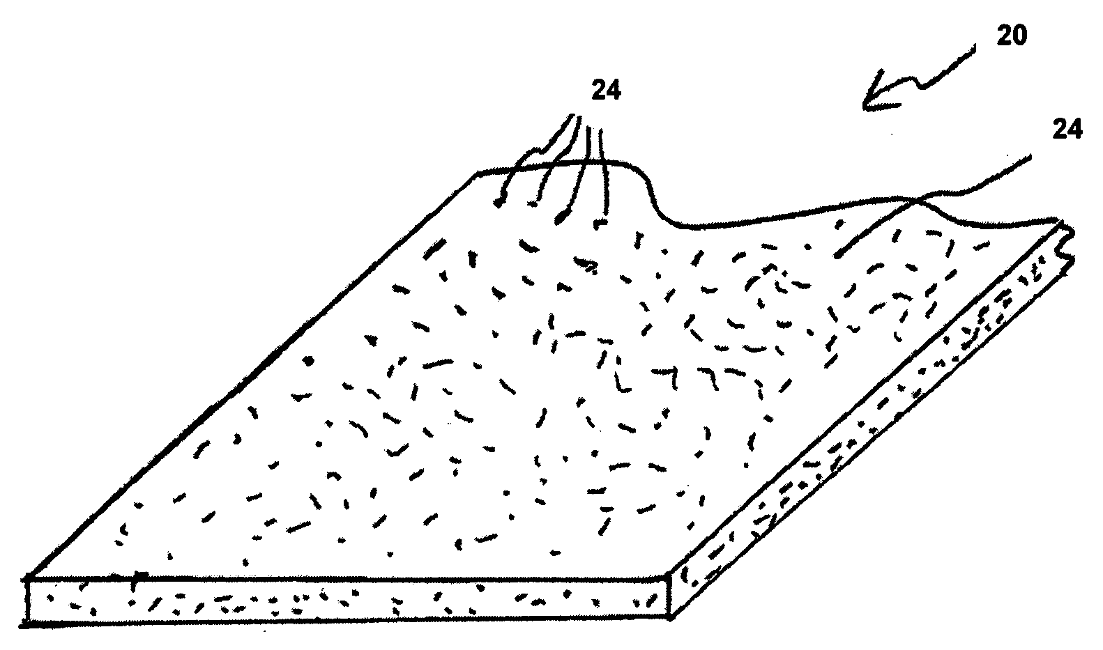
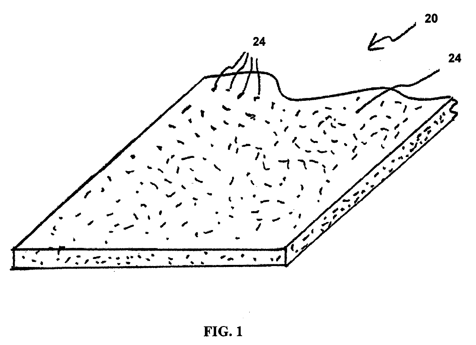
[0019]A fiber of the present invention was produced in the following manner.

[0020]A homopolymer PTFE fine powder resin was loaded to 5%, by weight, with the abrasive filler. The fine powder of homopolymer PTFE resin and abrasive filler were combined in a blender with an amount of lubricant (PD23 available from Brenntag Chemicals, Mülheim, Germany) until a uniform compound was obtained. The amount of lubricant used per pound of PTFE resin and filler was 22%. The homopolymer PTFE resin has a specific gravity of 2.148 to 2.164. The abrasive filler was alumina having a particle size ranging from 8 to 13 μm. The compound was compressed into a billet and extruded through a 1.4 mm gap die attached to a ram type extruder to form a coherent extrudate. A reduction ratio of 16 was used. The extrudate is passed over rollers and through calenders to compress the extrudate to a thickness of 254 μm and a width of 229 mm. The lubricant was volatilized and removed by passing the extrudate over a hea...

example 2

[0030]A fiber of the present invention was produced in the following manner.

[0031]A homopolymer PTFE fine powder resin was loaded to 5%, by weight, with the abrasive filler. The fine powder of homopolymer PTFE resin and abrasive filler were combined in a blender with an amount of lubricant (PD23 available from Brenntag Chemicals, Mülheim, Germany) until a uniform compound was obtained. The amount of lubricant used per pound of PTFE resin and filler was 22%. The homopolymer PTFE resin has a specific gravity of 2.153. The abrasive filler was silica having a particle size ranging from 8 to 13 μm. The compound was compressed into a billet and extruded through a 1.4 mm gap die attached to a ram type extruder to form a coherent extrudate. A reduction ratio of 16 was used. The extrudate is passed over rollers and through calenders to compress the extrudate to a thickness of 254 μm and a width of 229 mm. The lubricant was volatilized and removed by passing the extrudate over a heat can at 3...


PUM

PropertyMeasurementUnit
Temperatureaaaaaaaaaa

Abstract

Polytetrafluoroethylene (PTFE) flosses have abrasives added to the floss fiber that increase the abrasion to teeth surfaces, and thus result in a floss that provides enhanced cleaning of surfaces of teeth that face interstices between teeth. Floss fiber is formed by loading a PTFE resin with an abrasive filler. The PTFE resin and filler are processed to form a floss fiber with a surface that provide enhanced abrasion properties.

Description

FIELD OF THE INVENTION[0001]The present disclosure relates to dental floss, and more particularly dental floss made of polytetrafluoroethylene (PTFE) fibers that has abrasive components that facilitate cleaning of teeth.BACKGROUND OF THE INVENTION[0002]Dental floss has been known for many years, and is used to clean the interstitial spaces between a person's teeth. Dental floss in more recent times has been formed from PTFE, which provides a fiber that is thin enough to be inserted between teeth with relative ease, and is strong enough to provide a reliable flossing fiber. PTFE flosses have a number of advantages over conventional nylon flosses, including resistance to shredding (and its accompanying sticking of fiber shreds between teeth) and high lubricity. PTFE floss materials are traditionally formed from a thin, flat tape slit into single filament strands that may be folded prior to the spooling process.[0003]Such PTFE dental floss is characterized by a relatively smooth surfac...

Claims


Application Information

Patent Timeline
IPC IPC(8): A61C15/04B32B19/00
CPCA61C15/041Y10T428/29B29K2027/18B29C55/005
Inventor WILLIAMS, CHARLES T.HILL, KIMBERLY E.
Owner COLTEC IND
Why Eureka
Try Eureka