
Electrical connector canopy

Inactive Publication Date: 2009-10-01
HEBERT ROBERT J
View PDF14 Cites 6 Cited by
  • Summary
  • Abstract
  • Description
  • Claims
  • Application Information

AI Technical Summary

Benefits of technology

[0003]In light of the problems associated with the design and maintenance of certain CDMA base stations, it is a principal object of the invention to provide an electrical connector canopy for releasable attachment to the cabinet of a CDMA base station that shields external electrical connectors from: precipitation, airborne dust and dirt, insects, animals, and inadvertent human contact. Thus, a base station utilizing my canopy can be expected to operate longer without the need to repair or replace its associated electrical connectors or cables, saving substantial sums of money.
[0004]It is another object of the invention to provide an electrical connector canopy of the type described that can be quickly and easily installed upon a base station cabinet by one person with minimal instruction and without resort to any additional tools. The subsequent operation of the canopy is particularly intuitive.
[0006]Still another object of the invention is to provide an electrical connector canopy that provides strain relief to the electrical connectors that it covers.
[0007]It is an object of the invention to provide improved features and arrangements thereof in an electrical connector canopy for the purposes described that is lightweight in construction, inexpensive to manufacture, long lived, and dependable in use.

Problems solved by technology

While the cabinet adequately shields its contents from the weather, it does have one weak point: cables that transmit RF communications signals to and from the base station are joined to connectors located on the exterior of the cabinet.
These connectors, even when wrapped with insulative materials, are, unfortunately, prone to early failure due to corrosion brought about by the infiltration of precipitation and dirt.
Since the loss of signal through a single connector renders a base station inoperative, a serious maintenance challenge is presented to cellular communication providers that utilize Lucent 4401 base stations.

Method used


Image

  • Electrical connector canopy
  • Electrical connector canopy
  • Electrical connector canopy

Examples


Embodiment Construction

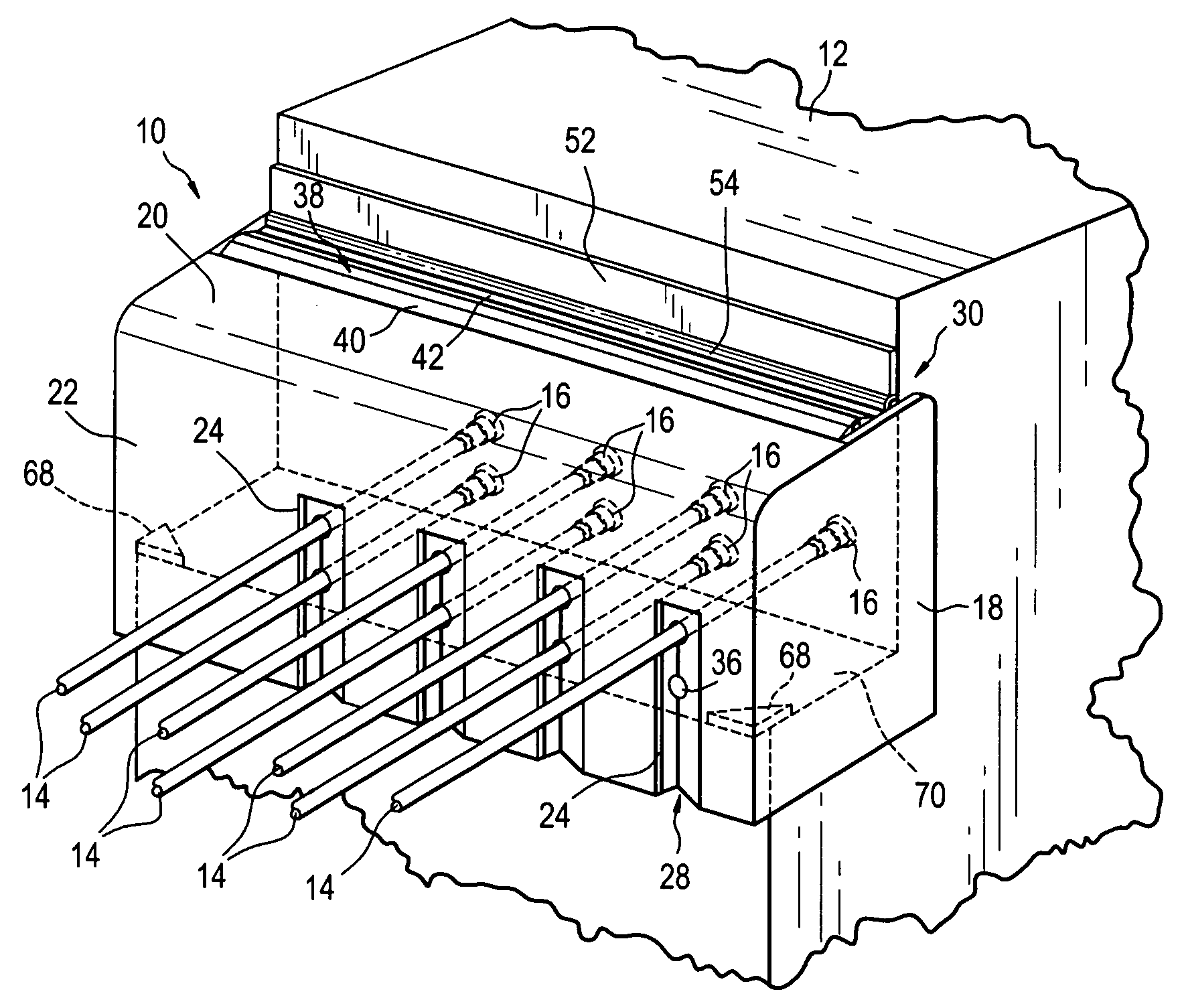
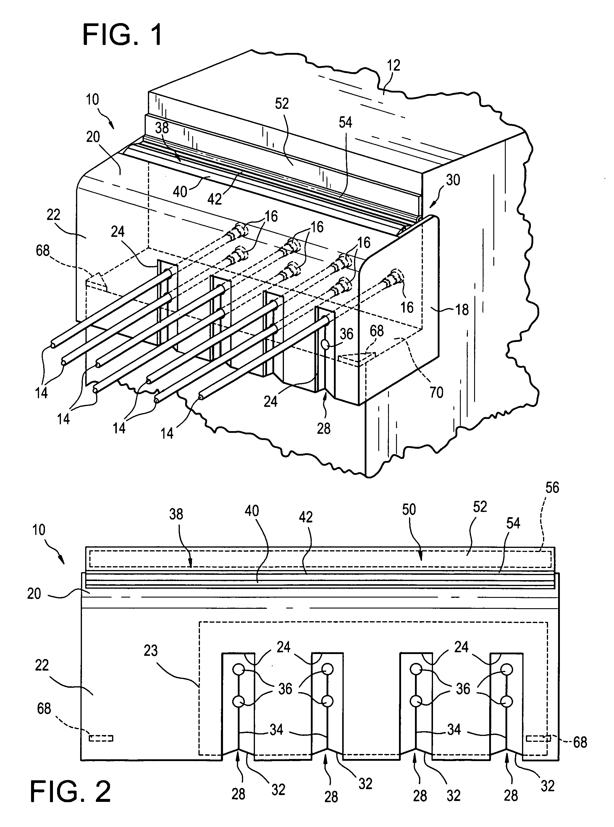
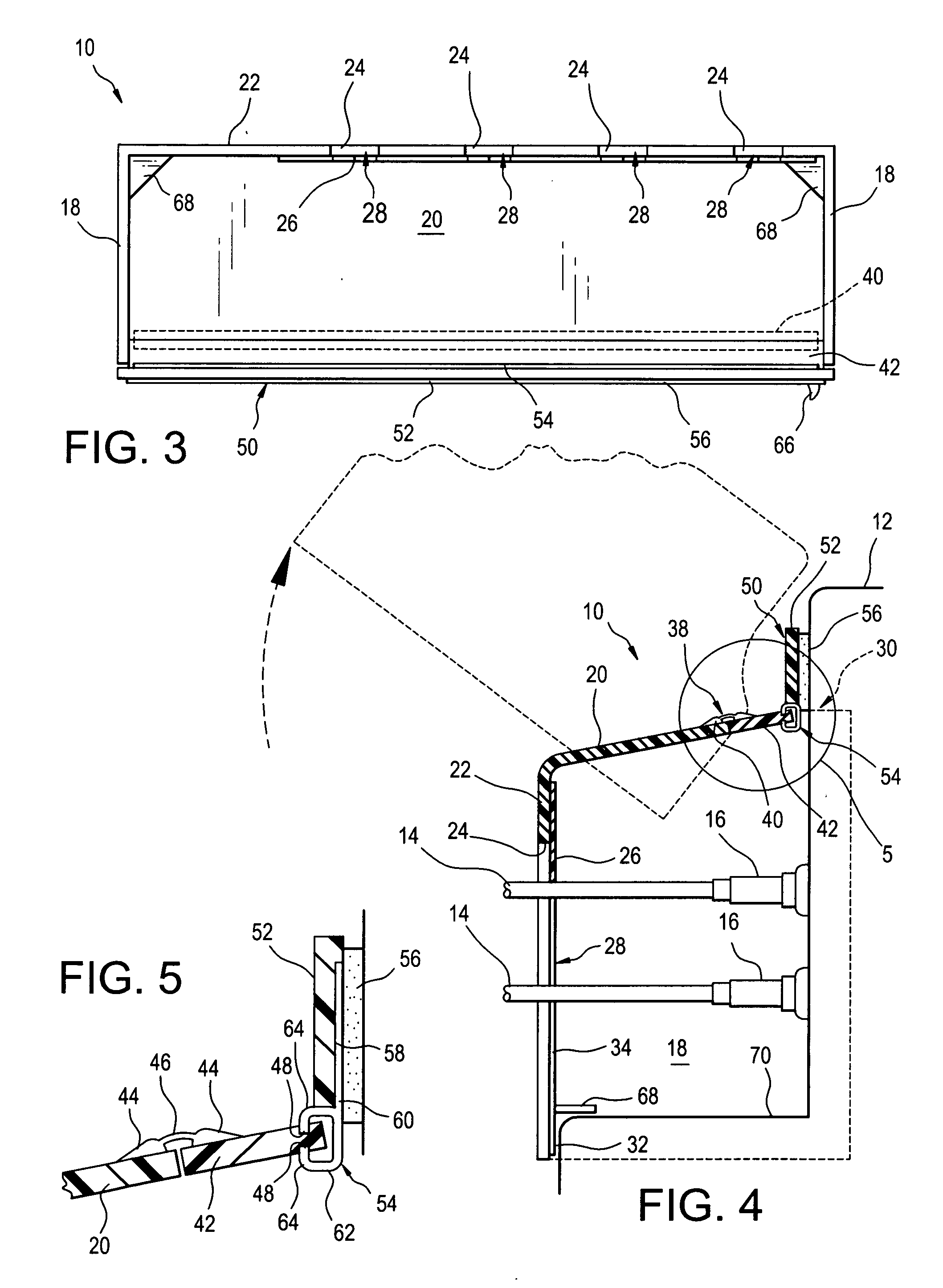
[0016]Referring now to the FIGS., an electrical connector canopy 10 shown to be mounted on a telecommunications base station cabinet 12 to which coaxial cables 14 are joined by means of cable connectors 16. Canopy 10 includes two, spaced-apart end walls 18 that are connected together by a top wall 20. A front wall 22 is connected to, and extends downwardly from, top wall 20. A number of vertical slots 24 are provided in front wall 22 that extend upwardly from the bottom thereof. A resilient sheet 26 is affixed to front wall 22 to prevent the passage of animals, dirt, and precipitation through slots 24. Sheet 26 is, however, provided with elongated openings 28 that extend along the centerlines of slots 24 to provide for the snug passage of cables 14.

[0017]Each of end walls 18 is a generally rectangular piece of ABS plastic being about 0.25 inches (6 mm) thick. Each end wall 18 measures about 11 inches (28 cm) from top to bottom and measures about 9 inches (23 cm) from front to back. ...


PUM


Abstract

An electrical connector canopy including a pair of spaced-apart, end walls. A top wall extends between and connects together the end walls. A front wall extends downwardly from and connects to the top wall. The front wall is provided with a number of vertical slots that extend upwardly from the bottom thereof. A resilient sheet is affixed to the front wall. The sheet is provided with a number of elongated openings, each of which extends upwardly along the centerline of a respective one of the slots.

Description

FIELD OF THE INVENTION[0001]The present invention relates generally to electricity, conductors and insulators, and, more particularly, to covers or face plates with closures for face plate openings.BACKGROUND OF THE INVENTION[0002]One popular CDMA base station, the Lucent 4401, is housed in a heavy-duty cabinet. While the cabinet adequately shields its contents from the weather, it does have one weak point: cables that transmit RF communications signals to and from the base station are joined to connectors located on the exterior of the cabinet. These connectors, even when wrapped with insulative materials, are, unfortunately, prone to early failure due to corrosion brought about by the infiltration of precipitation and dirt. Since the loss of signal through a single connector renders a base station inoperative, a serious maintenance challenge is presented to cellular communication providers that utilize Lucent 4401 base stations.SUMMARY OF THE INVENTION[0003]In light of the problem...

Claims


Application Information

Patent Timeline
IPC IPC(8): H02G3/14
CPCH02G3/22H02G3/14
Inventor HEBERT, ROBERT J.
Owner HEBERT ROBERT J
Learn More