Electric-powered vehicle and controlling method thereof

Inactive Publication Date: 2009-10-01
TOYOTA JIDOSHA KK
View PDF11 Cites 33 Cited by
  • Summary
  • Abstract
  • Description
  • Claims
  • Application Information

AI Technical Summary

Benefits of technology

[0032]In the present electric-powered vehicle, charging from a source outside the vehicle to the electric power storage apparatus is realized by using the first and second rotating electric machines, the first and second inverters provided respectively corresponding to them, and the inverter control portion. Therefore, with the present electric-powered vehicle, it is not necessary to include a separate charging converter, and reduction in the size of the vehicle as well as an improvement in the fuel efficiency owing to the reduction in the weight of the vehicle ca

Problems solved by technology

Therefore, if the driver forgets to charge the battery in the first place when he exits the vehicle despite the lowered SOC of the b

Method used


Image

  • Electric-powered vehicle and controlling method thereof
  • Electric-powered vehicle and controlling method thereof
  • Electric-powered vehicle and controlling method thereof

Examples


first embodiment

Second Variation of First Embodiment

[0140]The operation pattern of informing apparatus 102 may be changed based on whether or not the SOC of main battery SOC is smaller than the reference value representing lowering of the SOC of main battery B, so that the vehicle user is more surely informed about lowering of the SOC of main battery B.

[0141]FIG. 13 is another flowchart showing the control of informing apparatus 102 by control apparatus 60 shown in FIG. 1. The process shown in this flowchart is also called from the main routine and executed, at regular time intervals or every time a prescribed condition is satisfied.

[0142]Referring to FIG. 13, control apparatus 60 includes steps S22, S24, and S26 in place of step S20 in the process shown in FIG. 12. That is, when it is determined that the fuel remaining amount of engine 4 is not greater than the reference value representing lowering of the fuel remaining amount in step S15 (YES in step S15), control apparatus 60 determines whether ...

second embodiment

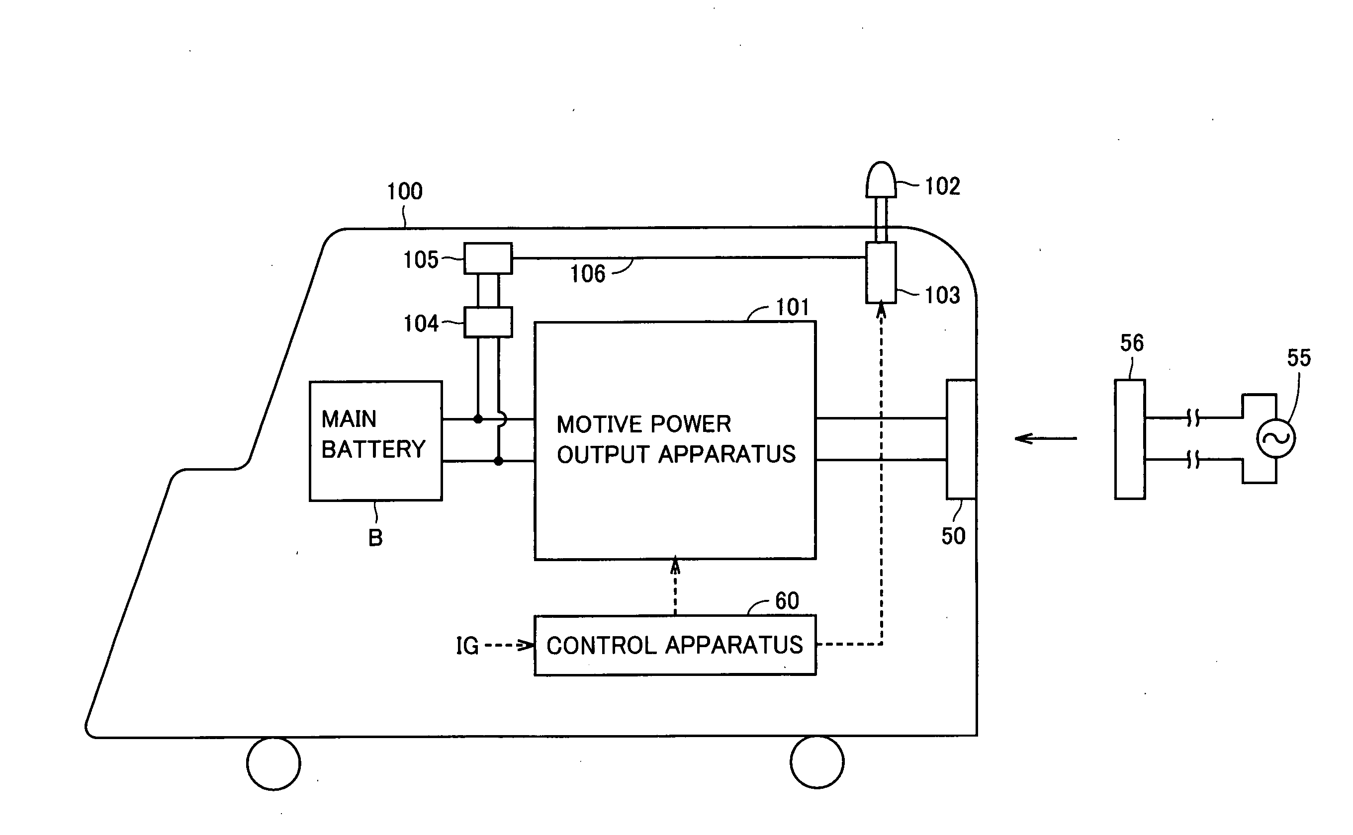
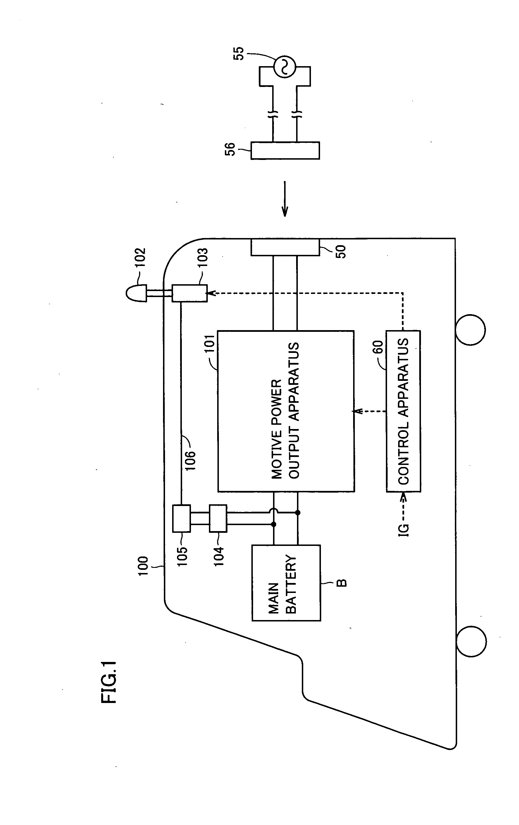
[0147]FIG. 14 is a schematic block diagram of a hybrid vehicle shown as one exemplary electric-powered vehicle according to a second embodiment of the present invention. Referring to FIG. 14, hybrid vehicle 100A further includes a seat sensor 107, and a control apparatus 60A in place of control apparatus 60, in the configuration of hybrid vehicle 100 in the first embodiment shown in FIG. 1.

[0148]Seat sensor 107 senses whether or not the driver is seated in the driver's seat. Seat sensor 107 outputs a signal of H level to control apparatus 60A when the driver is seated in the driver's seat, and outputs a signal of L level to control apparatus 60A when the driver is not seated in the driver's seat. As seat sensor 107, a load sensor disposed in the seat or an optical sensor optically sensing whether the driver is seated may be used.

[0149]Control apparatus 60A receives signal IG from the ignition key, and receives a detection signal from seat sensor 107. When control apparatus 60A deter...

third embodiment

[0157]FIG. 16 is a schematic block diagram of a hybrid vehicle shown as one exemplary electric-powered vehicle according to a third embodiment of the present invention. Referring to FIG. 16, hybrid vehicle 100B further includes a vehicle position detecting apparatus 108, and a control apparatus 60B in place of control apparatus 60A, in the configuration of hybrid vehicle 100A in the second embodiment shown in FIG. 14.

[0158]Vehicle position detecting apparatus 108 detects whether or not hybrid vehicle 100B is parked at the location where charging equipment is installed. Vehicle position detecting apparatus 108 may be, for example, a car navigation apparatus. Alternatively, it may sense that the vehicle is parked at the location where charging equipment is installed based on the communication with a radio apparatus (not shown) provided at the location where the charging equipment is installed.

[0159]When vehicle position detecting apparatus 108 detects that the vehicle is parked at the...


PUM


Abstract

When a control apparatus determines, based on a signal, that an ignition key has been turned to the OFF position, the control apparatus outputs to an actuator an operation command of an informing apparatus based on the SOC of a main battery. The informing apparatus is disposed at a location where it can easily be seen by the driver when the driver has exited from the vehicle, and driven by the actuator. The informing apparatus changes its projection amount from the external surface of the vehicle or an angle relative to the external surface of the vehicle based on the SOC of the main battery.

Description

TECHNICAL FIELD [0001]The present invention relates to an electric-powered vehicle, and particularly, to an electric-powered vehicle such as an electric vehicle or a hybrid vehicle incorporating as a motive power source a battery that can be charged and discharged.BACKGROUND ART [0002]In recent years, electric-powered vehicles such as electric vehicles or hybrid vehicles are receiving widespread attention as environmentally friendly vehicles. An electric vehicle uses an electric power storage apparatus (battery), an inverter, and an electric motor (motor) driven by the inverter as its motive power source. A hybrid vehicle uses, in addition to a conventional engine, a battery, an inverter and a motor driven by the inverter as its motive power source.[0003]In such an electric vehicle or hybrid vehicle incorporating a battery as a source of energy, it is necessary for the driver to grasp the state of charge (SOC) of the battery.[0004]Japanese Patent Laying-Open No. 7-87607 discloses a ...

Claims


Application Information

Patent Timeline
IPC IPC(8): B60W10/04B60W20/00B60K6/442B60L3/00B60W10/26H02P5/74
CPCB60L11/123Y02T90/14B60L11/1812B60L11/1814B60L11/1816B60L11/1861B60L15/007B60L2210/20B60L2220/14B60L2220/54B60W20/00B60W2510/244Y02T10/6217Y02T10/6269Y02T10/641Y02T10/7005Y02T10/7044Y02T10/705Y02T10/7077Y02T10/725Y02T90/127B60L11/14Y02T10/7072B60L53/14B60L53/22B60L50/61B60L50/16B60L53/24B60L58/12Y02T10/62Y02T10/64Y02T10/70Y02T10/72B60W2050/146B60K6/442B60W10/26B60W20/13B60W10/24Y02T90/12
Inventor OYOBE, HICHIROSAINAKAMURA, MAKOTO
Owner TOYOTA JIDOSHA KK
Why Eureka
Try Eureka