
Compression stocking applicator

a compression stocking and applicator technology, applied in the field of compression stocking applicators, can solve the problems of difficult difficult to do, and the ring does not provide a very easy application of compression stockings over the entire limb, and achieves the reduction of the thickness of the elongate member at the heel opening, high compression stocking, and sufficient rigidity.

Active Publication Date: 2009-10-01
EZY AS ABC PTY LTD
View PDF7 Cites 9 Cited by
  • Summary
  • Abstract
  • Description
  • Claims
  • Application Information

AI Technical Summary

Benefits of technology

[0020]It is an object of the invention to provide a stocking applicator which may overcome at least some of the above-mentioned disadvantages or provide a useful or commercial choice.
[0035]It is envisaged that the applicator will be relatively rigid during use. However, the applicator may have a degree of flex if desired.
[0042]In some further embodiments of the invention, an inner surface of the elongate member may be provided with one or more raised portions. The raised portions may comprise any suitable form, although in some embodiments of the invention, the raised portions comprise one or more ribs. The ribs may be located at any point on the inner surface of the elongate member. In one embodiment of the present invention, the ribs are located on the inner surface of the interconnecting wall. In a preferred embodiment of the invention, the ribs are located adjacent the heel opening in the elongate member. The number and placement of these ribs serves to allow the thickness of the elongate member at the heel opening to be reduced while still retaining sufficient rigidity to load and apply a high compression stocking.

Problems solved by technology

The stockings are typically made of relatively fine elastic material and it is this property that also makes the stockings difficult to apply as it is necessary to keep the stocking open and to fit the stocking about the person's foot and leg.
Firstly, once the stocking has been fitted, the ring needs to be removed by sliding it back over the person's foot, and some people may find it difficult to do this and particularly to pick up the ring afterwards.
Also, the ring does not provide a very easy application of the compression stocking over the entire limb (that is the foot, ankle and calf).
Most of these “wire” type applicators suffer from the disadvantage that they are designed to be placed on the floor and the patient is required to lower their foot into the device.
Therefore, this type of applicator can generally not be used if the patient is sitting, has one leg crossed over the other leg, or lying down in bed.
Some type of applicators comprise a rigid or substantially rigid tube which may have some advantages over the simple ring, but suffer from the same disadvantage of needing to be removed back over the foot and not being entirely satisfactory in fitting the stocking.
Quite complicated mechanical stocking applicators are also known but these applicators are expensive to manufacture, difficult to use, and difficult, if not impossible, to transport with the person.
A disadvantage with many applicators is also in the easy use of the applicator.
That is, many applicators are not particularly suited to easily fit a stocking over the person's foot, past the person's heel, over the ankle and along the person's calf.
It should be appreciated that many people find this particular maneuver extremely difficult.
It is found that it can be quite painful for many people to use a stocking applicator due to the need to twist the person's limb during application, or to bend or stretch etc during the application process.
A disadvantage with other applicators is that it is somewhat fiddly to fit the stocking to the applicator prior to applying the stocking to a person's limb.
As the stocking can be quite flimsy and also quite expensive, it is not satisfactory to have a system where the stocking can be torn.
Other types of applicators are suitable only for the lower limbs and are not particularly suited for upper limbs.

Method used


Image

  • Compression stocking applicator
  • Compression stocking applicator
  • Compression stocking applicator

Examples


Embodiment Construction

[0053]It will be appreciated that the drawings have been provided for the purposes of illustrating preferred embodiments of the present invention and that the invention should not be considered to be limited solely to the features as shown in the drawings.

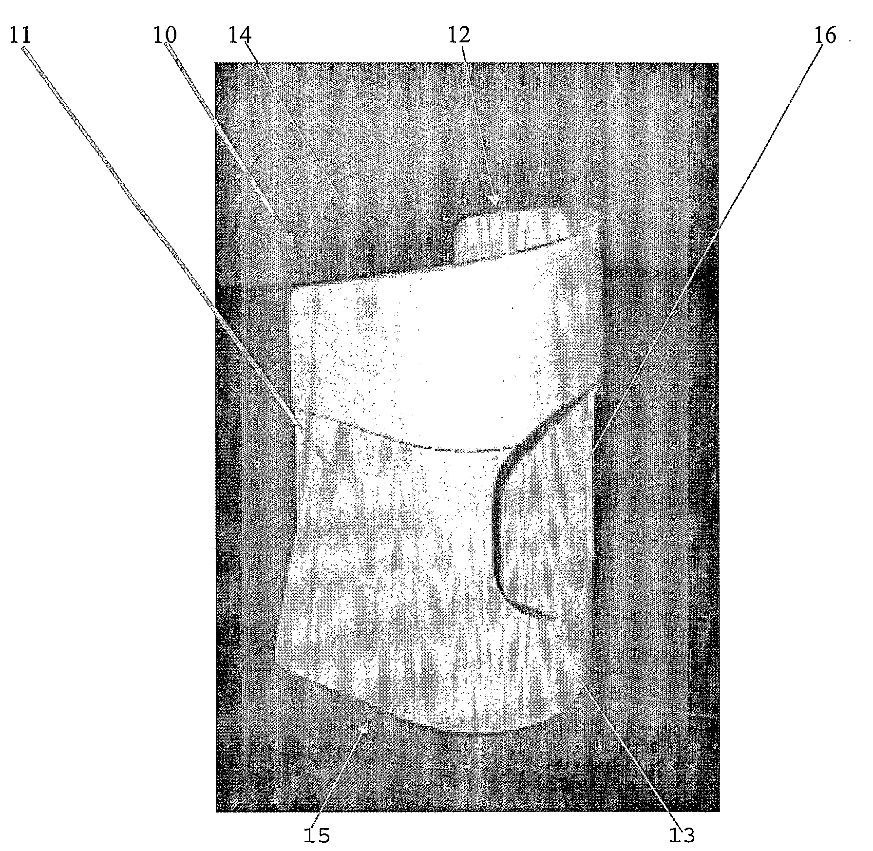
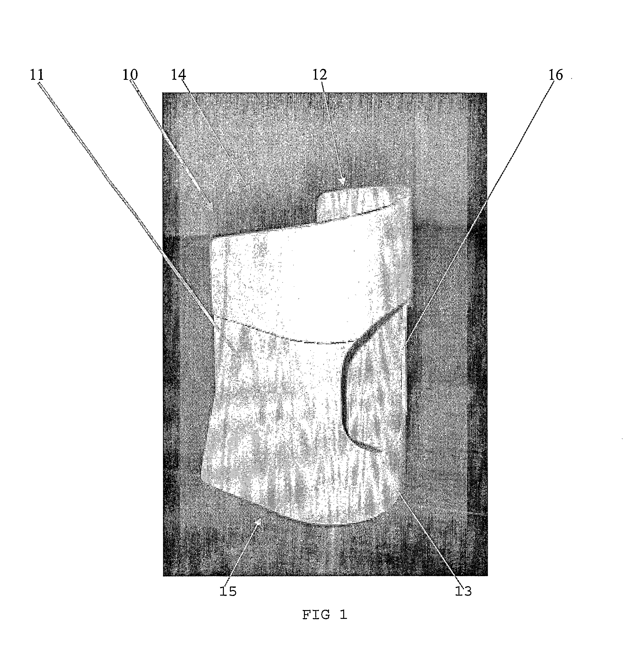
[0054]Referring initially to FIG. 1, there is illustrated a compression stocking applicator 10. Applicator 10, in the particular embodiment, is made of smooth polyvinyl chloride and has a length of between 15-30 cm. Applicator 10 is somewhat U-shaped and comprises a pair of opposed sidewalls 11, 12 and an interconnecting wall 13. In the embodiment, the applicator 10 is a unitary structure.

[0055]The design of applicator 10 is such that the interconnecting wall 13 is smooth and curved. The sidewalls 11, 12 are substantially parallel to each other.

[0056]Applicator 10 has an “upper” end 14 and a “lower” end 15. Lower end 15 is square cut such that the applicator can stand in an upright position as illustrated in FIG. 1. Upper end 14 is...


PUM


Abstract

A medical compression stocking applicator comprises an elongate member which comprises a pair of opposed side-walls and an interconnecting wall and therefore may be substantially U-shaped in cross-section and is open at each end, the elongate member comprising a heel opening between the ends of the elongate member, said heel opening extending entirely through the elongate member, the heel opening adapted to support a person's heel during application of a stocking.

Description

FIELD OF THE INVENTION[0001]This invention is directed to a small and easily used device to allow a person to put on a compression stocking. Although the invention will be described with reference to a compression stocking, the device can also be used on other types of stockings, socks etc where there is an advantage in using the device. The device can also be used to fit a compression bandage to a person's arm or somewhere else.BACKGROUND ART[0002]A compression stocking generally comprises an elastic sock which can be fitted to a person to provide compression. The stockings are generally used to improve circulation. Compression stockings are well known in the art and are sometimes called elastic stockings, medical stockings, compression socks, compression / tubular bandages and the like.[0003]These stockings are used for burns victims, on patients before having operations, to prevent deep vein thrombosis, for patients with vascular diseases, for treatment of topical ulcers, for varic...

Claims


Application Information

Patent Timeline
IPC IPC(8): A47G25/90
CPCA47G25/905A61F13/085A61F13/041A47G25/908
Inventor HILDEBRANDT, BARRY GEORGE
Owner EZY AS ABC PTY LTD
Learn More