
Two-dimensional code having rectangular region provided with specific patterns for specification of cell postions and distinction from background

a two-dimensional code and rectangular region technology, applied in the field of two-dimensional codes, can solve the problems of reducing the number of cells which can be assigned, and achieve the effect of increasing the number of cells for such data

Active Publication Date: 2009-10-01
DENSO WAVE INC
View PDF10 Cites 26 Cited by
  • Summary
  • Abstract
  • Description
  • Claims
  • Application Information

AI Technical Summary

Benefits of technology

The present invention provides a two-dimensional code that can better distinguish itself from the background and reduce the number of cells assigned to data other than error correction. This allows for more cells to be assigned for data. The code has a rectangular region delineated from the background by borders, with code blocks composed of cells arranged in a specific pattern and error-correction code blocks containing cells that correct errors. The error-correction code blocks can be arranged along the borders of the rectangular region. The invention also includes compressed-data code blocks that are arranged contiguously to the borders of the rectangular region. The borders of the rectangular region can include a first border along which the first specific pattern is arranged and one or more of the error-correction code blocks are arranged along the first border.

Problems solved by technology

However, in this case, it is required to use a large number of cells as the cells which should be assigned to the specific patterns, which are not data to be decoded and data for error correction.
Hence, it cannot help but to reduce the number of cells which can be assigned to both data to be decoded and data for error correction.

Method used


Image

  • Two-dimensional code having rectangular region provided with specific patterns for specification of cell postions and distinction from background
  • Two-dimensional code having rectangular region provided with specific patterns for specification of cell postions and distinction from background
  • Two-dimensional code having rectangular region provided with specific patterns for specification of cell postions and distinction from background

Examples


first embodiment

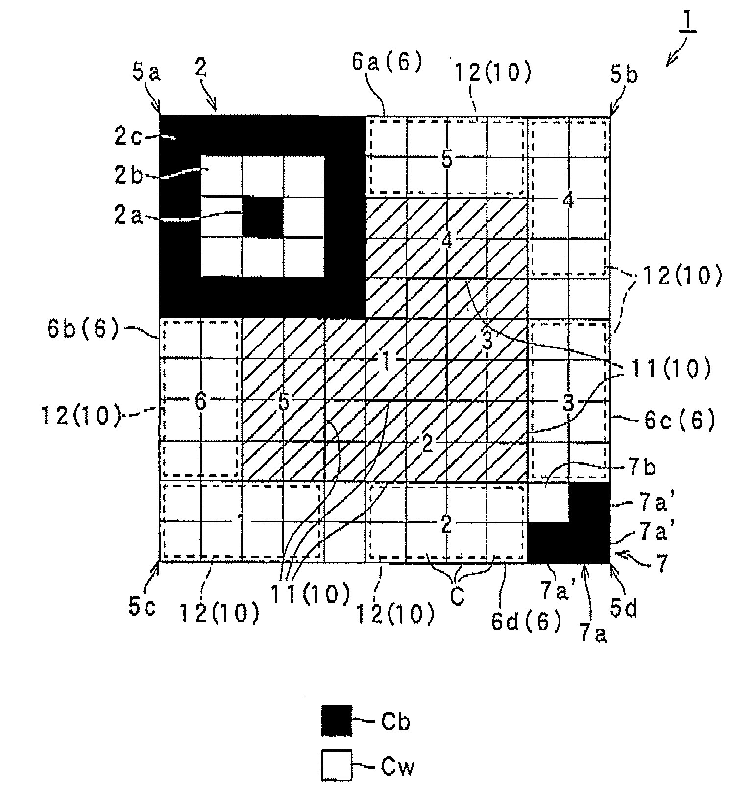
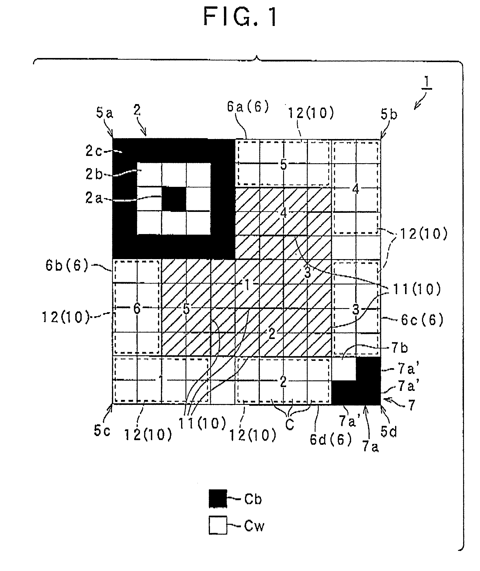
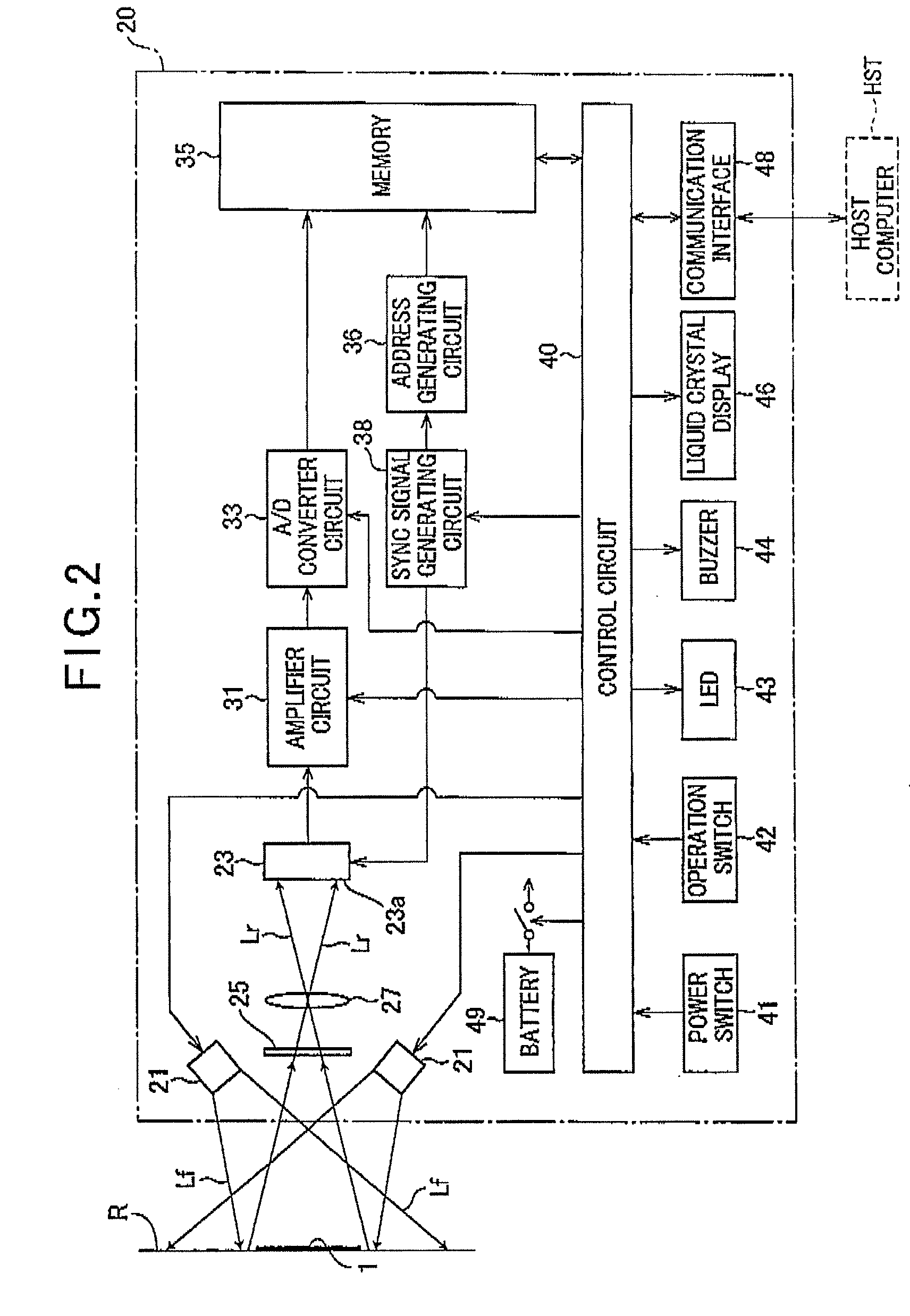
[0035]Referring to FIGS. 1-3, a first embodiment of a two-dimensional code according to the present embodiment will now be described.

[0036]FIG. 1 conceptually illustrates the two-dimensional code according to the first embodiment, in which the positions of error-correction code blocks 12, which will be described later, are conceptually shown by dashed lines and the positions of data code blocks 11 are conceptually shown by solid-line areas with hatching thererein. In FIG. 1, practical cell structures of respective code blocks 10 are omitted from being detailed.

[0037]As shown in FIG. 1, the two-dimensional code 1 (hereinafter referred to as the 2D code 1), which is structurally composed of a plurality of cells C arranged (mapped, drawn, represented, depicted, or present) in a matrix, comprises a plurality of code blocks 10, a first specific pattern 2, and an end pattern 7 from the functional viewpoint. Practically, the 2D code 1 is composed of an aggregation of cells arranged in a ma...

second embodiment

[0080]Referring to FIG. 4, a second embodiment of the two-dimensional (2D) code according to the present invention will now be described. In the second embodiment and other embodiments following thereafter, the same or identical components as or to those in the first embodiment will be given the same reference numbers for the sake of a simplified or omitted explanation.

[0081]FIG. 4 conceptually illustrates a 2D code 120 adopted by the second embodiment. In FIG. 4, the positions of the error-correction code blocks 12 are conceptually illustrated by dashed lines, while the positions of compressed-data code blocks 13, which will be described later, are conceptually illustrated by solid lines and hatching the areas enclosed by the solid lines. In addition, FIG. 4 is omitted from detailing the cell configurations of the respective code blocks 10.

[0082]The 2D code 120 of the present embodiment is the same in construction as the 2D code shown in FIG. 1 except for the configurations and arr...

third embodiment

[0092]Referring to FIG. 5, a third embodiment will now be described.

[0093]FIG. 5 conceptually illustrates a 2D code 130 adopted by the third embodiment. In FIG. 5, the positions of the error-correction code blocks 12 are conceptually illustrated by dashed lines, while the positions of the data code blocks 11 are conceptually illustrated by solid lines and hatching the areas enclosed by the solid lines. In addition, FIG. 5 is omitted from detailing the cell configurations of the respective code blocks 10.

[0094]The 2D code 130 differs from that shown in FIG. 1 in that the code 130 has a second specific pattern 131 later described as well as error-correcting blocks 12 and data code blocks 11, which blocks 12 and 13 are shaped and arranged differently from those shown in FIG. 1. The remaining features, that is, the configuration of the first specific pattern 2, the entire matrix configuration of the code 130, the shape and length of the borders 6, and the positions and shapes of the cor...


PUM


Abstract

A two-dimensional code having a rectangular region is provided. In the rectangular region, there are a plurality of code blocks, a first specific pattern, and error-correction code blocks. Each code block is composed of a plurality of cells aggregated together and formed to have both a specified corner in the rectangular region and the plurality of code blocks arranged in the rectangular region. The specific pattern is used to specify the positions of the cells. The error-correction code blocks are contained in the code blocks and formed to correct an error. The error-correction code blocks are arranged contiguously to part of the borders of the rectangular region. The part of the borders is displaced from the first specific pattern. Compressed data code blocks are also arranged in the same way as the error-correction code blocks.

Description

CROSS-REFERENCE TO RELATED APPLICATION[0001]This application is based on and claims the benefit of priorities from earlier Japanese Patent Application Nos. 2008-083487 and 2008-224862 filed Mar. 27, 2008 and Sep. 2, 2008, the descriptions of which are incorporated herein by reference.BACKGROUND OF THE INVENTION[0002]1. Technical Field of the Invention[0003]The present invention relates to a two-dimensional code, and in particular, to a two-dimensional code having a rectangular region delineated by a plurality of cells and formed to have specific patterns for specifying the positions of cells in the rectangular region and distinguishing the code from the background.[0004]2. Related Art[0005]Various types of two-dimensional codes have been known and commercially used, which are composed of a plurality of cells arranged in a matrix form. In order to read the two-dimensional codes, a two-dimensional code reader is necessary. This reader usually captures a two-dimensional image data whic...

Claims


Application Information

Patent Timeline
Patent Type & Authority Applications(United States)
IPC IPC(8): G06K19/06
CPCG06K19/06037G06K2019/06225G06K2019/06262G06K19/0614G06K7/1417G06K19/06046G06K19/06056G06K7/1408
Inventor USHIJIMA, TAKAOMIZUKOSHI, HIROAKIKITA, HAYATO
Owner DENSO WAVE INC
Learn More