
Method of manufacturing semiconductor devices

a manufacturing method and semiconductor technology, applied in the direction of coatings, transistors, chemical vapor deposition coatings, etc., can solve the problems of deteriorating reliability affecting the stability of a semiconductor device, and generating leakage current deteriorating reliability, etc., to achieve stable structure, high crystallization temperature, and stable

Active Publication Date: 2010-04-27
SAMSUNG ELECTRONICS CO LTD
View PDF9 Cites 14 Cited by
  • Summary
  • Abstract
  • Description
  • Claims
  • Application Information

AI Technical Summary

Benefits of technology

The patent text describes methods and materials for manufacturing semiconductor devices with a high dielectric layer that has a high dielectric constant and reduces leakage current. The methods involve providing a zirconium source and removing non-adsorbed portions through a purging process. The resulting high dielectric layer has a stable structure with zirconium, oxygen, carbon, and nitrogen stably combined. The semiconductor devices made using these methods have improved performance and reliability.

Problems solved by technology

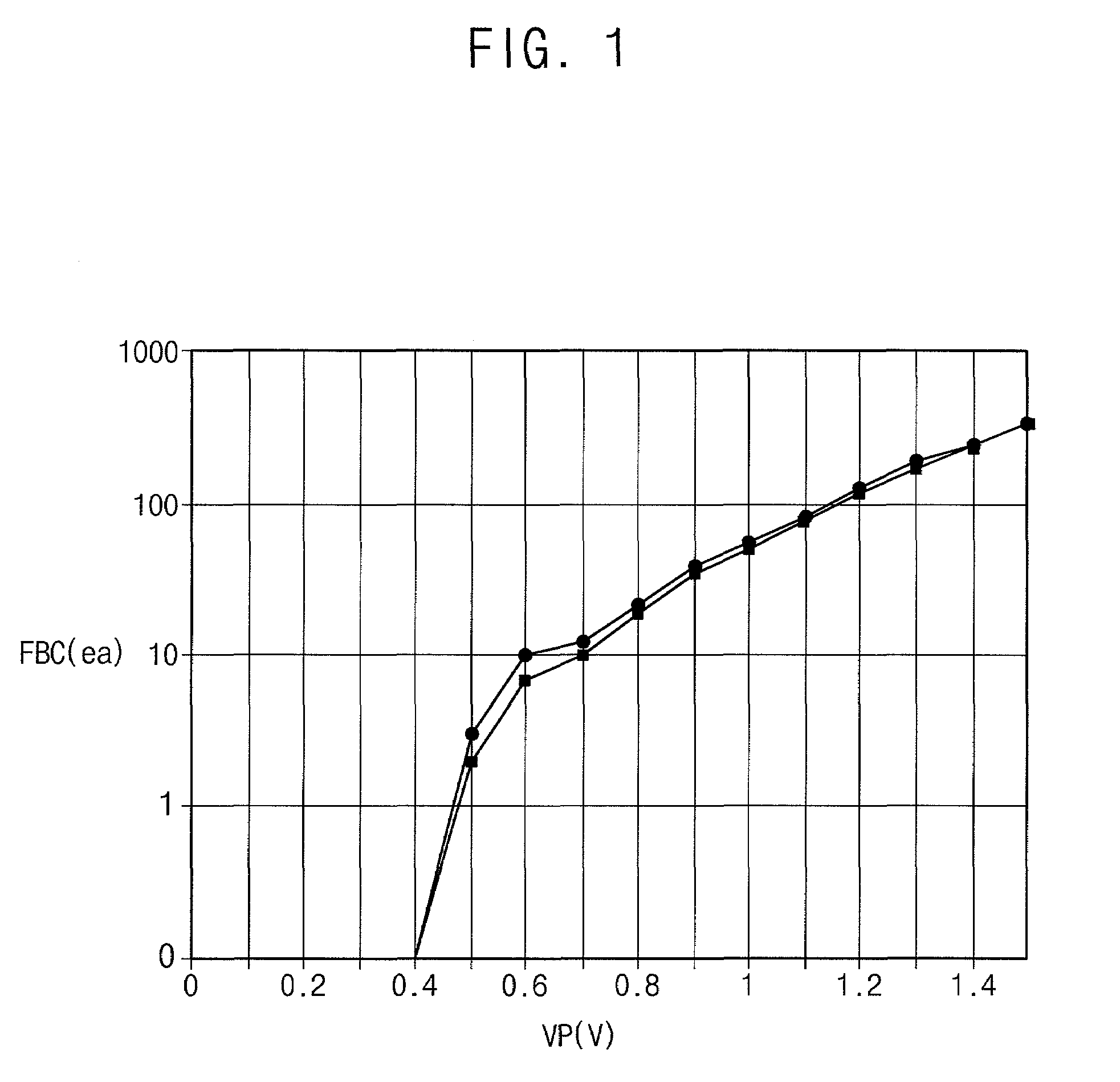
When crystallization of a dielectric layer occurs, a threshold voltage of a gate may not be uniform along a channel length, and a leakage current deteriorating reliability of a semiconductor device may be generated.
However, a zirconium oxide layer may have some difficulties with regard to deteriorating characteristics of a semiconductor device.
Therefore, when a zirconium oxide dielectric layer is used, an increase in temperature in a thermal process may be limited.

Method used


Image

  • Method of manufacturing semiconductor devices
  • Method of manufacturing semiconductor devices
  • Method of manufacturing semiconductor devices

Examples


Embodiment Construction

[0039]Various example embodiments will be described more fully hereinafter with reference to the accompanying drawings, in which some example embodiments are shown. Example embodiments may, however, be embodied in many different forms and should not be construed as limited to the example embodiments set forth herein. In the drawings, the sizes and relative sizes of layers and regions may be exaggerated for clarity.

[0040]It will be understood that when an element or layer is referred to as being “on,”“connected to” or “coupled to” another element or layer, it may be directly on, connected or coupled to the other element or layer or intervening elements or layers may be present. In contrast, when an element is referred to as being “directly on,”“directly connected to” or “directly coupled to” another element or layer, there are no intervening elements or layers present. Like numerals refer to like elements throughout. As used herein, the term “and / or” includes any and all combinations...


PUM

PropertyMeasurementUnit
dielectric constantaaaaaaaaaa
temperatureaaaaaaaaaa

Abstract

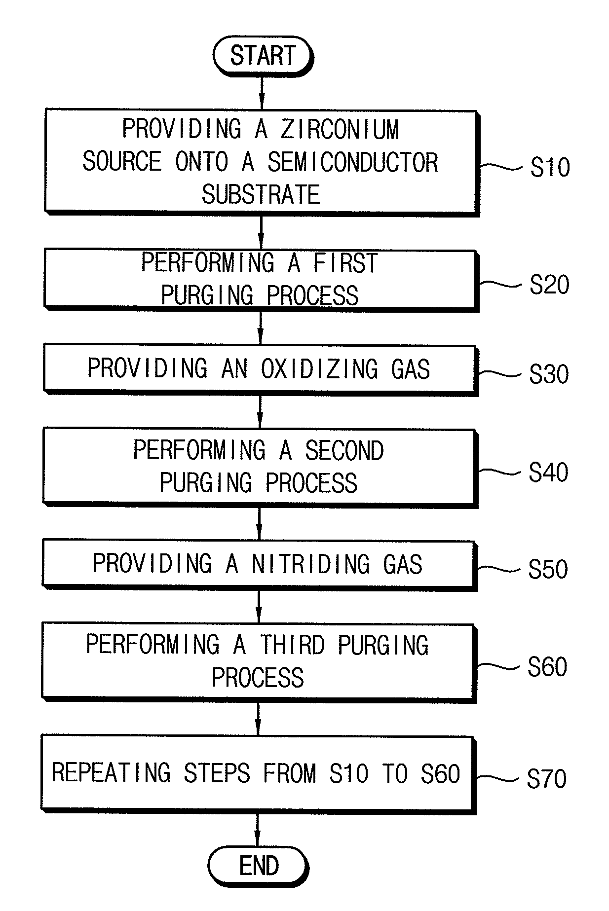
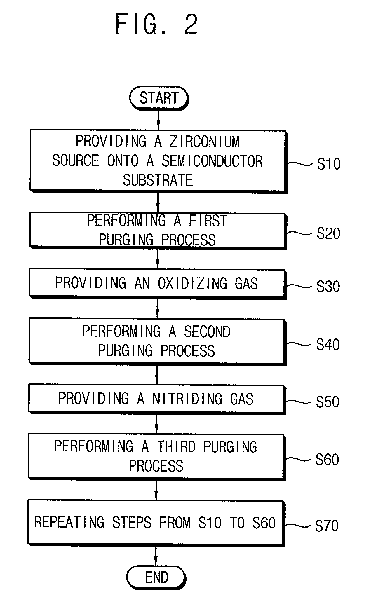
In semiconductor devices and methods of manufacturing semiconductor devices, a zirconium source having zirconium, carbon and nitrogen is provided onto a substrate to form an adsorption layer of the zirconium source on the substrate. A first purging process is performed to remove a non-adsorbed portion of the zirconium source. An oxidizing gas is provided onto the adsorption layer to form an oxidized adsorption layer of the zirconium source on the substrate. A second purging process is performed to remove a non-reacted portion of the oxidizing gas. A nitriding gas is provided on the oxidized adsorption layer to form a zirconium carbo-oxynitride layer on the substrate, and a third purging process is provided to remove a non-reacted portion of the nitriding gas.

Description

CROSS-REFERENCE TO RELATED APPLICATIONS[0001]This application claims priority under 35 USC §119 to Korean Patent Application No. 2008-23059, filed on Mar. 12, 2008, the contents of which are hereby incorporated by reference in their entirety.BACKGROUND[0002]1. Technical Field[0003]Example embodiments relate to semiconductor devices having a dielectric layer of a high dielectric constant and to a method of manufacturing semiconductor devices.[0004]2. Description of the Related Art[0005]As a result of semiconductor devices becoming more highly integrated, the area of a unit cell has been significantly reduced, and also the operational voltage has been lowered as well. Accordingly, a dielectric layer having a high dielectric constant (high-k) has been applied to the semiconductor devices to enhance electrical storage performance and / or to suppress leakage current through the dielectric layer.[0006]Generally, a high-k dielectric layer has a thin equivalent oxide thickness and a high die...

Claims


Application Information

Patent Timeline
Patent Type & Authority Patents(United States)
IPC IPC(8): H01L21/3205H01L21/4763H10B12/00
CPCC23C16/30C23C16/308C23C16/405C23C16/45529H01L28/55C23C16/45542H01L21/3141H01L21/3145H01L21/31641C23C16/45531H01L21/02274H01L21/02189H01L21/0228H01L21/02205H01L21/022H10B12/00
Inventor KIM, WEON-HONGSONG, MIN-WOOPARK, PAN-KWIPARK, JUNG-MIN
Owner SAMSUNG ELECTRONICS CO LTD
Learn More